
Device and method for removing sulfur trioxide from smoke

A sulfur trioxide and flue gas technology, applied in chemical instruments and methods, separation methods, and dispersed particle separation, etc., can solve the problems of flue corrosion at the denitrification inlet, front-end denitrification device, air preheater hazards, and more pollutant emissions. , to achieve the effect of reducing SO3 content, reducing clean emissions and high removal efficiency

Inactive Publication Date: 2015-08-26
BEIJING GUODIAN LONGYUAN ENVIRONMENTAL ENG
View PDF5 Cites 48 Cited by
  • Summary
  • Abstract
  • Description
  • Claims
  • Application Information

AI Technical Summary

Problems solved by technology

[0009] The object of the invention is a method for removing SO in flue gas 3 The device and method, to solve the SO in the prior art 3 The problem of harm to the front-end denitrification device and air preheater; also solve the problem of SO 3 Corrosion of the denitrification inlet flue, and the discharge of pollutants in the flue gas

Method used


Image

  • Device and method for removing sulfur trioxide from smoke
  • Device and method for removing sulfur trioxide from smoke
  • Device and method for removing sulfur trioxide from smoke

Examples


Embodiment 1

[0028] Alkaline absorbent choose magnesium hydroxide Mg(OH) 2 Particles with an average particle size of 40 μm.

[0029] The flue gas temperature at the denitrification inlet is 350°C, SO 3 Content 20ppm, according to flue gas conditions and magnesium oxide composition, determine the chemical reaction equivalent ratio SO 3 : Mg(OH) 2 =1:3, through a higher stoichiometric ratio to ensure SO 3 removal efficiency.

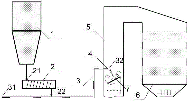
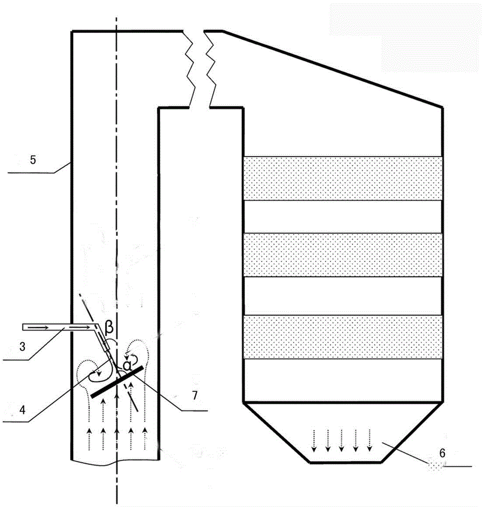
[0030] Such as figure 1 As shown, a method for removing SO from flue gas 3 In the process system, the magnesium hydroxide absorbent is stored in the silo 1 in the form of powder, and the feeding rate of the absorbent is controlled by the screw feeder 2, and the pneumatic conveying system 3 uses compressed air to transport magnesium hydroxide particles to the injection device 4. Spray magnesium hydroxide particles into the denitrification inlet flue 5 . Magnesium hydroxide is uniformly mixed with the flue gas in the denitrification flue, and part of the SO in t...

Embodiment 2

[0034] The difference between this embodiment and embodiment 1 is that sodium bicarbonate is used as the alkaline absorbent, and the particle size of the absorbent is 60 μm.

[0035] The alkalinity of sodium bicarbonate alkaline absorbent is higher than that of magnesium hydroxide, so the chemical equivalent ratio SO3:NaHCO3=1:5, under the design conditions, the removal efficiency of SO3 is 90%.

Embodiment 3

[0037] The difference between this example and Example 1 is that calcium hydroxide (Ca(OH)2) is used as the alkaline absorbent, and the particle size of the absorbent is 40 μm.

[0038] The alkalinity of calcium hydroxide is slightly weaker, so the chemical equivalent ratio of SO3:Ca(OH)2=1:8, under the design conditions, the removal efficiency of SO3 is 65%.


PUM

PropertyMeasurementUnit
Particle sizeaaaaaaaaaa
The average particle sizeaaaaaaaaaa
Particle sizeaaaaaaaaaa

Abstract

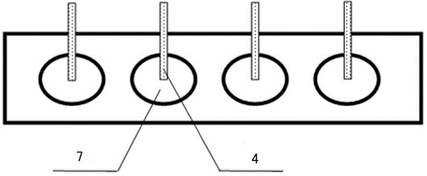
The invention discloses a device for removing sulfur trioxide from smoke. The device comprises a bin, a screw feeder, a smoke delivery pipe, a spray gun, a denitration inlet flue, a denitration reactor and a spoiler, wherein the screw feeder is provided with a feeding opening and a discharging opening, and the feeding opening is connected with the bin and used for controlling the discharging rate of an absorbent; the smoke delivery pipe is provided with a smoke inlet and a smoke outlet, and the discharging opening is connected with the smoke delivery pipe; the smoke outlet is connected with the spray gun, and the spray gun is used for spraying the absorbent for strong alkaline particles; the denitration inlet flue is used for mixing the absorbent with smoke, and the smoke outlet and the spray gun are positioned in the flue; the denitration reactor is connected with the denitration inlet flue. The device can be applied to a coal firing unit of a thermal power plant, effectively reduce the SO3 content, reduce the influence of the sulfur trioxide on the denitration device and an air pre-heater, and reduce pollutants to realize smoke clean emission.

Description

technical field [0001] The invention relates to a device and method for removing sulfur trioxide in flue gas, belonging to the field of air pollutant control. Background technique [0002] A large amount of pollutants are produced in the process of burning coal. Because the coal contains a certain concentration of sulfur, a certain concentration of SO will be generated in the final exhaust gas. 2 and SO 3 . [0003] SO 3 The formation mechanism of SO mainly includes the following parts. During the combustion process in the furnace, a part of the sulfur in the coal is directly converted into SO 3 ; During the heat exchange process of the tail heating surface, the flue gas is catalyzed and oxidized by the metal pipe wall and fly ash, and a part of SO 2 will be oxidized to SO 3 ; For units with newly added SCR denitrification devices, the denitrification catalyst also has a strong catalytic oxidation effect, making a part of SO 2 is oxidized to SO 3 . Usually for coal-...

Claims


Application Information

Patent Timeline
IPC IPC(8): B01D53/83B01D53/50B01D53/75B01D53/56
Inventor 陈振宇庄烨郑鹏刘科伟姚宣
Owner BEIJING GUODIAN LONGYUAN ENVIRONMENTAL ENG
Learn More