Two-phase bioretention pond with synchronous phosphorous and nitrogen removal function and construction method thereof

A technology of synchronous nitrogen and phosphorus removal and bioretention ponds, applied in sustainable biological treatment, chemical instruments and methods, biological water/sewage treatment, etc., can solve problems such as rainwater resource loss, building roof runoff pollution, etc.

Active Publication Date: 2015-09-02
BEIJING UNIV OF CIVIL ENG & ARCHITECTURE
View PDF8 Cites 13 Cited by
  • Summary
  • Abstract
  • Description
  • Claims
  • Application Information

AI Technical Summary

Problems solved by technology

[0021] Aiming at the shortcomings of traditional bioretention tanks in the prior art, the purpose of the present invention is to optimize and improve the removal mechanism of nitrogen and phosphorus in bioretention tanks, and design a new type of bioretention tank that c...

Method used


Image

  • Two-phase bioretention pond with synchronous phosphorous and nitrogen removal function and construction method thereof
  • Two-phase bioretention pond with synchronous phosphorous and nitrogen removal function and construction method thereof
  • Two-phase bioretention pond with synchronous phosphorous and nitrogen removal function and construction method thereof

Examples


Embodiment 1

[0068] Embodiment 1: the screening of filler

[0069] Selection of suitable filler is crucial for phosphorus removal. The amount of phosphorus contained in the filler itself has a great influence on the migration and transformation of phosphorus in the bioretention system. Fillers with a high phosphorus content index have a small absorption capacity for phosphorus. When the phosphorus content index is close to saturation, it will not only affect the phosphorus absorption capacity of the filler, but also seriously increase the phosphorus concentration in the effluent. Therefore, fillers with moderate phosphorus content should be selected, so as to ensure the normal growth of plants and receive better phosphorus removal effect.

[0070] The fillers used in this research are zeolite, quartz sand, medical stone, ceramsite, anthracite, aluminum sludge, river sand, fruit shell, activated carbon, fly ash, slag, etc. For desorption experiments, according to the experimental results,...

Embodiment 2

[0083] Example 2: Determining the layout of the two-phase area

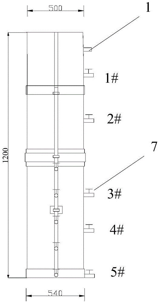
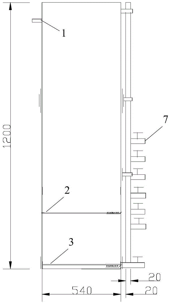
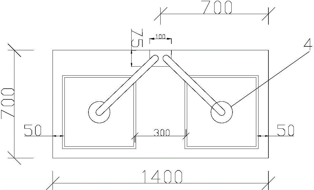
[0084] The experimental device used in this example is as figure 1 -5. The device is an experimental model of biological retention enhanced denitrification and phosphorus removal; device length × width × height = 500mm × 500mm × 1200mm; from top to bottom, it is planting soil layer, filling layer and gravel layer. The container of the device is welded and formed by plexiglass, and the inner wall of the device is roughened. A water outlet 7 is arranged on the wall 8 of the test container. In the device, an upper perforated plate 2 is installed between the packing layer and the gravel layer and a geotextile is laid. The cloth prevents the plant soil from spilling down into the gravel layer. The bottom of the device is provided with an upflow tube connected to the nozzle 4, and a flow regulating valve 5 is arranged on the upflow tube; the upflow tube is a DN20 / UPVC bonding tube, and the upflow tube is fixed vert...

Embodiment 3

[0095] A two-phase bioretention tank, from top to bottom are planting soil layer (thickness 200mm), packing layer and gravel layer, the packing layer is composed of zeolite + quartz sand + aluminum sludge + river sand in a volume ratio of 3:1:1 : 5 components, the thickness of the packing layer is 600mm, the thickness of the gravel layer is 300mm, and a perforated collection pipe with a diameter of 100mm is buried at the bottom of the gravel layer. The bottom of the packing layer is at a height of 5cm upwards. The principle of the two-phase bioretention tank constructed by the present invention to treat runoff is shown in Image 6 .

[0096] The water quality used for testing includes indicators such as total phosphorus, ammonia nitrogen, nitrate nitrogen, and total nitrogen. Water treatment experiment results: the effect of two-phase bioretention tank on TP, NH 4 -N, NO 3 The removal rates of -N and TN are 88.22%, 86.67%, 60.80% and 68.35%, respectively, and the effect of...


PUM

PropertyMeasurementUnit
Thicknessaaaaaaaaaa
Particle sizeaaaaaaaaaa
Thicknessaaaaaaaaaa

Abstract

The invention provides a construction method of a two-phase bioretention pond with a synchronous phosphorous and nitrogen removal function. The construction method includes screening of filler and setting of a two-phase reaction area. Filler high in total phosphorous adsorption efficiency is screened according to filler characteristic and adsorption experiment, the two-phase reaction area containing the filler comprises an aerobic reaction area used for removing phosphorus, ammonia nitrogen and organic nitrogen and an anoxia reaction area used for removing nitrate, water with known nitrogen and phosphorous content is injected from the upper side of the bioretention pond, and influences on nitrogen and phosphorous effect from altitude of the anoxia reaction area are shown by measuring nitrogen and phosphorous content in water samples from water outlets of different altitudes. In order to solve the existing problems of the bioretention pond, runoff nitrogen and phosphorous removal effect of bioretention is synchronously improved by reinforcing denitrification and filler adsorption in the bioretention pond. The construction method is applied to rainwater treatment of overland runoff of roads and city open spaces and construction roofs.

Description

technical field [0001] The invention belongs to the field of environmental protection, and in particular relates to a method for constructing a device with synchronous denitrification and phosphorus removal functions and the obtained device. Background technique [0002] Water eutrophication is one of the major water environment problems China is currently facing, and has become an important bottleneck restricting China's economic development. The excessive input and enrichment of nitrogen and phosphorus in water often lead to the deterioration of aquatic ecological environment. About 1 / 2 of the nitrogen and phosphorus pollutants received by urban river water bodies come from pollution carried by urban rainfall runoff, and 2 / 3 of the river water environment loses due functions due to rainfall runoff nitrogen and phosphorus pollution. Control runoff rainwater Nitrogen and phosphorus pollution is of great significance. [0003] Conventional bioretention tanks can effectively...

Claims


Application Information

Patent Timeline
IPC IPC(8): C02F3/30C02F3/32
CPCY02W10/10
Inventor 许萍张雅君张建强孙丽华何俊超王俊岭
Owner BEIJING UNIV OF CIVIL ENG & ARCHITECTURE
Why Eureka
Try Eureka