Check patentability & draft patents in minutes with Patsnap Eureka AI!

Process for reducing SO2 emission concentration of sulfur recovery device

A sulfur recovery and SO2 technology, applied in the direction of sulfur preparation/purification, etc., can solve the problems of increasing pipeline and equipment size, increasing process gas volume, pipeline and equipment corrosion, etc., so as to avoid the increase of pipeline and equipment size and reduce gas consumption. Low gas volume and low operating cost

Active Publication Date: 2015-12-09
CHINA PETROLEUM & CHEM CORP
View PDF4 Cites 9 Cited by
  • Summary
  • Abstract
  • Description
  • Claims
  • Application Information

AI Technical Summary

Problems solved by technology

[0009] The existing sulfur recovery technology can meet the GB16297-1996 "Comprehensive Emission Standard of Air Pollutants", but cannot meet the requirements of the new environmental protection standard that will be implemented in 2014
Existing liquid sulfur degassing technology The stripping gas for liquid sulfur degassing is usually air, steam, Claus tail gas and nitrogen. Steam is easy to cause corrosion of pipelines and equipment, and external gas supply sources will increase the gas volume of the process gas, thereby increasing pipelines and equipment. Size; H contained in Claus tail gas 2 S will dissociate H from liquid sulfur 2 S approaches equilibrium, liquid sulfur cannot satisfy H 2 The index requirement of S is less than 10ppm
The existing liquid sulfur degassing treatment adopts incinerator incineration technology, and the waste gas contains H 2 Sulfur-containing substances such as S and sulfur steam are directly introduced into the incinerator for treatment, and the sulfur-containing substances are burned and converted into SO 2 , so that the flue gas SO 2 Emission concentration increased by 100-300mg / m 3 , unable to meet the upcoming emission standards

Method used


Image

  • Process for reducing SO2 emission concentration of sulfur recovery device
  • Process for reducing SO2 emission concentration of sulfur recovery device
  • Process for reducing SO2 emission concentration of sulfur recovery device

Examples


Embodiment 1

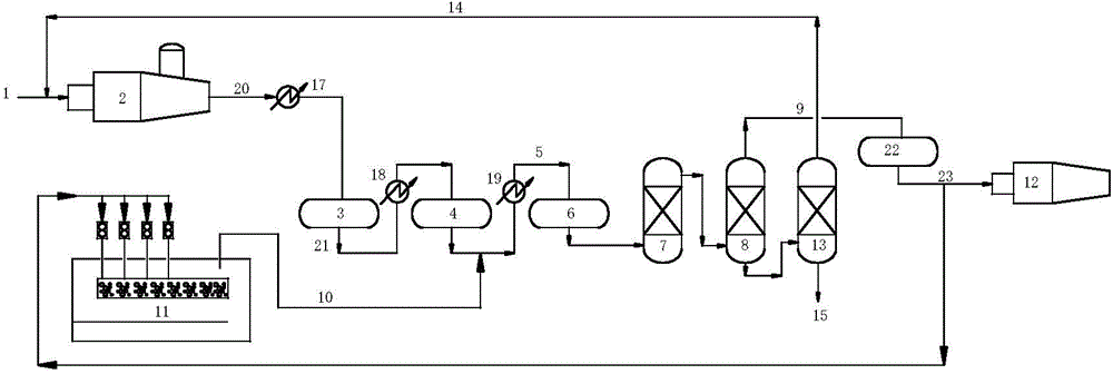
[0057] process such as figure 1shown. The process includes thermal reaction section, catalytic reaction section and tail gas purification treatment section.

[0058] In the thermal reaction section, the acid gas 1 containing 94 (v / v)% hydrogen sulfide is partially burned in the reactor 2 and converted to sulfur dioxide. At a high temperature of 1260°C, hydrogen sulfide and sulfur dioxide undergo a Claus reaction to generate elemental sulfur and reactor tail gas. 20. After being cooled by the primary condenser 17 (outlet temperature 166°C), the elemental sulfur enters the liquid sulfur pool 11 to obtain liquid sulfur. The volume content of the reaction furnace tail gas 20 sulfur-containing compounds is: H 2 S: 8.12%, SO 2 : 4.03%, organic sulfur: 0.48%.

[0059] Reactor tail gas 20 enters the primary reactor 3 of the catalytic reaction section (reaction conditions: temperature 320°C, space velocity 800h -1 ) and secondary reactor 4 (reaction conditions: temperature 234 ° C...

Embodiment 2

[0062] process such as image 3 shown. The process includes thermal reaction section, catalytic reaction section and tail gas purification treatment section.

[0063] In the thermal reaction section, the acid gas 1 containing 94 (v / v)% hydrogen sulfide is partially burned in the reactor 2 and converted to sulfur dioxide. At a high temperature of 1260°C, hydrogen sulfide and sulfur dioxide undergo a Claus reaction to generate elemental sulfur and reactor tail gas. 20. After being cooled by the primary condenser 17 (outlet temperature 166°C), the elemental sulfur enters the liquid sulfur pool 11 to obtain liquid sulfur. The volume content of the reaction furnace tail gas 20 sulfur-containing compounds is: H 2 S: 8.12%, SO 2 : 4.03%, organic sulfur: 0.48%.

[0064] Reactor tail gas 20 enters the primary reactor 3 of the catalytic reaction section (reaction conditions: temperature 320°C, space velocity 800h -1 ) and secondary reactor 4 (reaction conditions: temperature 234 ° ...

Embodiment 3

[0067] process such as figure 2 shown. The process includes thermal reaction section, catalytic reaction section and tail gas purification treatment section.

[0068] In the thermal reaction section, the acid gas 1 containing 94 (v / v)% hydrogen sulfide is partially burned in the reactor 2 and converted to sulfur dioxide. At a high temperature of 1260°C, hydrogen sulfide and sulfur dioxide undergo a Claus reaction to generate elemental sulfur and reactor tail gas. 20. After being cooled by the primary condenser 17 (outlet temperature 166°C), the elemental sulfur enters the liquid sulfur pool 11 to obtain liquid sulfur. The volume content of the reaction furnace tail gas 20 sulfur-containing compounds is: H 2 S: 8.12%, SO 2 : 4.03%, organic sulfur: 0.48%.

[0069] Reactor tail gas 20 enters the primary reactor 3 of the catalytic reaction section (reaction conditions: temperature 320°C, space velocity 800h -1 ) and secondary reactor 4 (reaction conditions: temperature 234 °...


PUM


Abstract

The present invention belongs to the technical field of sulfur recovery, in particular relates to a process for reducing SO2 emission concentration of a sulfur recovery device. The process is as follows: sulfur compounds in Claus tail gas from a catalytic reaction zone firstly is converted by hydrogenation into H2S in a hydrogenation reactor under the action of a hydrogenation catalyst, then the Claus tail gas is cooled in a quench tower, then enters into an amine liquid absorber for absorption of H2S in the hydrogenation tail gas; purified tail gas out from the amine liquid absorber enters into a desulphurization reactor containing a bifunctional zinc oxide desulfurizer for purification, part of the purified tail gas is introduced into a liquid sulfur pool to be used as a gas stripping gas of molten sulfur degasification, after the molten sulfur degasification exhaust gas is extracted, the molten sulfur degasification exhaust gas and a reacting furnace tail gas are mixed, and enter into a primary condenser for sulfur recovery processing, or the molten sulfur degasification exhaust gas and a primary reactor tail gas are mixed, and enter into a secondary condenser for sulfur recovery processing, or the molten sulfur degasification exhaust gas and the Claus tail gas are mixed, and enter into a third condenser for sulfur recovery processing, the rest of the purified tail gas is introduced into an incinerator for incineration and emissions, and final flue gas SO2 emission concentration of the sulfur recovery device can be reduced to 50mg / m<3> or less.

Description

technical field [0001] The invention belongs to the technical field of sulfur recovery, in particular to a sulfur recovery device for reducing SO 2 Emission concentration process. Background technique [0002] SO 2 It is one of the most important environmental pollutants and the main cause of acid rain. SO 2 It can destroy the physiological functions of plants, slow down the growth of crops and forests, and the human body can inhale high concentrations of SO 2 Gas, will have a strong stimulating effect on the respiratory tract, so SO 2 As the main air pollutant emission control technology has been widely valued. In recent years, SO 2 The discharge has caused 40% of my country's land area to be harmed by acid rain, and the annual loss caused by it is as high as 110 billion yuan. According to the current emission control level, by 2020, the SO emissions from the petroleum refining industry 2 It will reach 126993t / a. Therefore, control pollution, reduce SO 2 Emissions...

Claims


Application Information

Patent Timeline
IPC IPC(8): C01B17/04
Inventor 刘爱华刘剑利张义玲陶卫东刘增让徐翠翠张艳松张玉红
Owner CHINA PETROLEUM & CHEM CORP
Features
  • R&D
  • Intellectual Property
  • Life Sciences
  • Materials
  • Tech Scout
  • Unparalleled Data Quality
  • Higher Quality Content
  • 60% Fewer Hallucinations
Learn More