RSD-based pulse power supply module

A technology of pulse power supply and charging power supply, which is applied in the direction of electric pulse generator circuit and energy storage element to generate pulses, etc., which can solve the problems of large stray parameters of the circuit, short service life, slow switching speed, etc., and achieve high output current density, Effects of reducing parasitic inductance and reducing wire length

Active Publication Date: 2015-12-09
HUAZHONG UNIV OF SCI & TECH
View PDF4 Cites 1 Cited by
  • Summary
  • Abstract
  • Description
  • Claims
  • Application Information

AI Technical Summary

Problems solved by technology

Under the impetus of national defense, economic and other fields, the increase of the on-state current rise rate di/dt of the switch will approach the working limit of the switch, and the performance of the switch greatly limits the progress in this field
[0003] In recent years, semiconductor switches such as reverse switching transistors (RSD), pulse thyristors, and insulated gate bipolar transistors (IGBTs) have gradually entered the field of pulse power; spark gap switches have high withstand voltage and large flow, but short service life; Bipolar transistors can withstand high-speed switching, high withstand voltage, and strong current. They are important

Method used


Image

  • RSD-based pulse power supply module
  • RSD-based pulse power supply module
  • RSD-based pulse power supply module

Examples


Embodiment 1

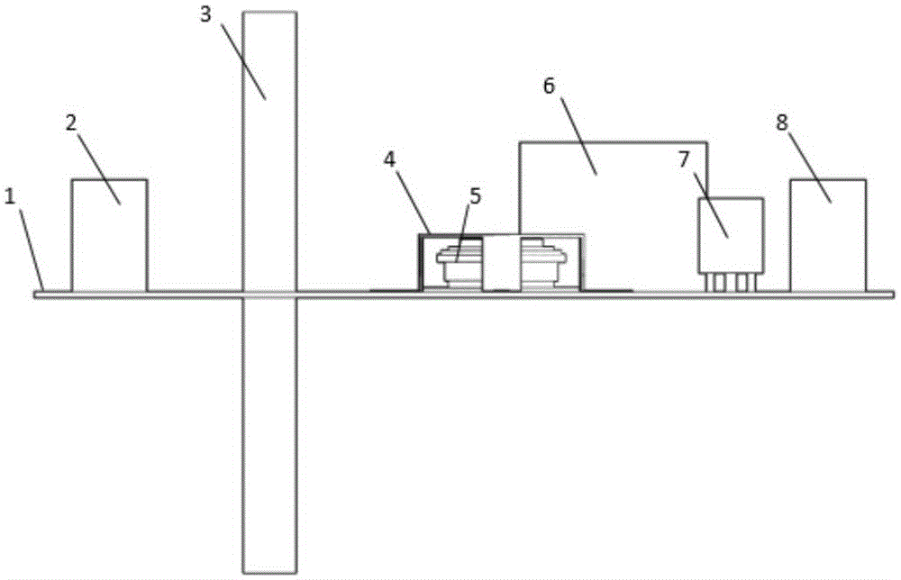
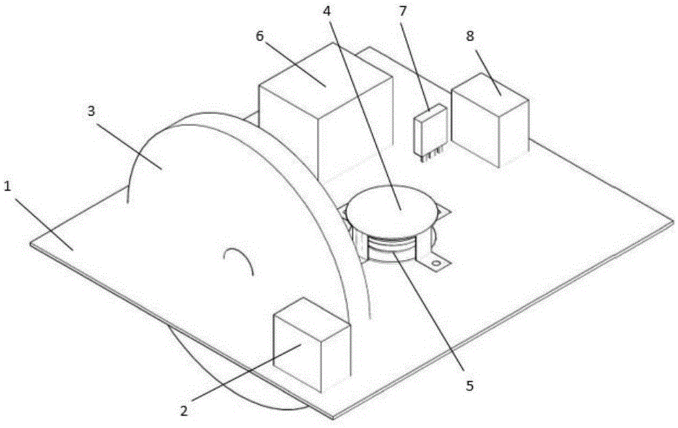
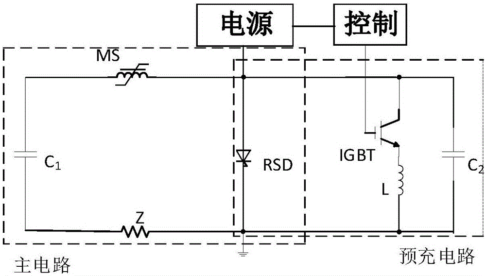
[0034] In Embodiment 1, in order to avoid the interference of the high current of the main circuit on the control module, the control module is formed into a separate board, which is composed of a general-purpose IGBT drive circuit and a TMS320X28 series DSP. The DSP outputs two complementary PWM waves, which are sent to the pre-charging source 6 respectively. And the driving circuit of IGBT7, when the pre-charging source 6 receives a high-level signal, IGBT7 receives a complementary low-level signal; when charging, the IGBT is disconnected, and the IGBT is turned on after charging, and the pulse power supply starts to work. Control the on-off of the charging power supply 6 and IGBT7 to realize the repetition frequency work of the pulse power supply;

[0035] In Example 1, the soldering of RSD5 and the surrounding copper foil 4 and PCB1 adopts a reflow soldering process, and the solder is made of lead-containing solder, which is soft and helps to reduce thermal stress; wherein,...

Embodiment 2

[0049] The difference between embodiment 2, embodiment 3 and embodiment 1 is that the tube core parameters of the RSD that the pulse power supply adopts are different, and the tube core of the RSD that embodiment 1 adopts is 1 inch, and the tube core of the RSD that embodiment 2 adopts is 2 inches. Inch, the tube core of the RSD that embodiment 3 adopts is 3 inches, and the size of RSD tube core is bigger, and corresponding RSD encapsulation profile is bigger, and the relevant parameters such as the withstand voltage of RSD are higher, and the output current of pulse power supply and repetition frequency are higher. High; as the size of the RSD changes, the parameters of the surrounding copper foil covering the RSD change accordingly.


PUM

PropertyMeasurementUnit
Thicknessaaaaaaaaaa
Diameteraaaaaaaaaa
Diameteraaaaaaaaaa

Abstract

The invention discloses an RSD-based pulse power supply module. The module comprises a main capacitor, a magnetic switch, an RSD, a charging power supply, a switch pipe, a pre-charge capacitor, a pre-charge inductor and a control module and is characterized in that the main capacitor, the magnetic switch, the RSD, the charging power supply, the switch pipe, the pre-charge capacitor and the pre-charge inductor are integrated in one PCB; and the RSD is fixed on the PCB by a surrounded copper foil. By integrating the RSD power switch, the charging power supply, the capacitor and the magnetic switch in the PCB, all elements work cooperatively and length of a wire is reduced, so stray parameters like parasitic inductance of the power supply is reduced; the rate of rise di/dt of on-state current of the RSD is increased; in addition, the surrounded copper foil is used for welding and fixing the RSD, thereby facilitating acceleration of heat radiation of the RSD and increasing of current channels on the PCB; and copper foil is capable of equally distributing current trends, so current carrying capacity of the pulse power supply module is improved.

Description

technical field [0001] The invention belongs to the technical field of high-power and high-density pulses, and more particularly relates to an RSD-based pulse power supply module. Background technique [0002] High-power pulse power supply (megawatt-level power supply) is to quickly compress, convert or directly release the stored high-density energy to the load. It is widely used in controlled thermonuclear fusion, high-pressure dust removal, organic wastewater treatment and other fields; existing The pulse power supply technology in the technology uses the capacitor energy storage discharge method, and most of them use mechanical spark gaps or non-contact ion devices such as hydrogen thyratrons as discharge switches. During the switch-on process, the switch must withstand a large on-state current rise rate di / dt. Driven by the fields of national defense and economy, the increase of the on-state current rise rate di / dt of the switch will approach the working limit of the s...

Claims


Application Information

Patent Timeline
IPC IPC(8): H03K3/57
Inventor 梁琳王石磊陈材
Owner HUAZHONG UNIV OF SCI & TECH
Why Eureka
Try Eureka