High-voltage DC transmission converter valve single-row valve tower

A high-voltage direct current transmission and converter valve technology, which is applied in the direction of converting AC power input into DC power output, output power conversion devices, electrical components, etc. , expensive land occupation and other problems, to achieve the effect of eliminating corrosion of waterway metal joints, improving space utilization, and saving land occupation costs

Active Publication Date: 2015-12-30
GLOBAL ENERGY INTERCONNECTION RES INST CO LTD +2
View PDF5 Cites 11 Cited by
  • Summary
  • Abstract
  • Description
  • Claims
  • Application Information

AI Technical Summary

Problems solved by technology

First, the increase in voltage requires an increase in the withstand voltage capacity of the converter valve, an increase in the number of series series of converter valve components, an increase in the size of the converter valve module and the insulation distance between layers of the valve tower, and objectively requires the conversion The appearance size of the valve tends to increase accordingly, but the cost of occupying space for the converter valve hall is becoming more and more expensive. Hall area ratio
Second, the main water pipe between the layers of the converter valve is connected between the two-layer modules of the valve tower, and its two ends must bear the inter-layer voltage of the converter valve. The increase in voltage will increase the leakage current in the inter-layer water pipe, affecting the layer The static distribution of the voltage between the valves and the electrical corrosion of the metal joints in the water pi

Method used


Image

  • High-voltage DC transmission converter valve single-row valve tower
  • High-voltage DC transmission converter valve single-row valve tower
  • High-voltage DC transmission converter valve single-row valve tower

Examples


Embodiment Construction

[0036] In order to understand the present invention better, below in conjunction with description Attached pictureAnd example content of the present invention is described further.

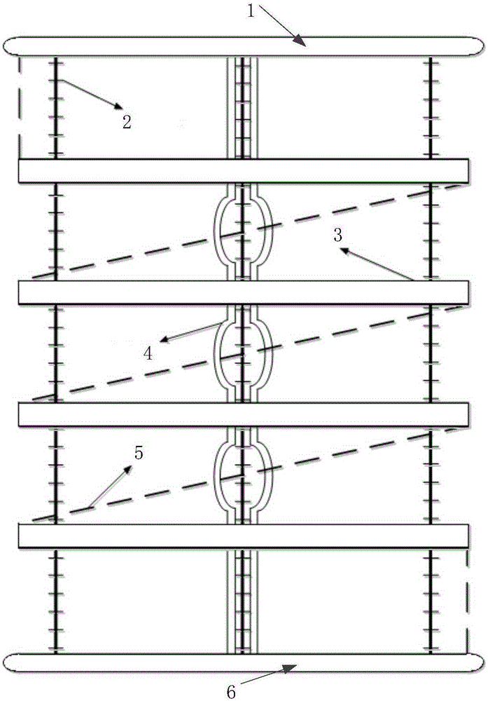
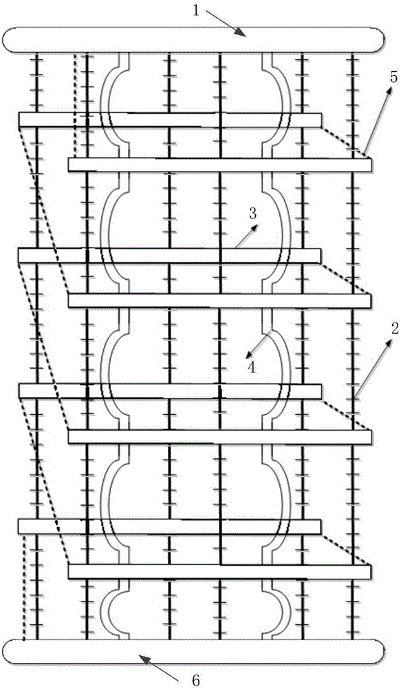
[0037] Single row valve tower of high voltage direct current transmission converter valve provided by the present invention Such as Figure 4 As shown, it is mainly composed of a top shield 1 , a bottom shield 6 , a converter valve module 3 , a main water pipe 4 , an interlayer busbar 5 , an interlayer insulator 2 and a suspension insulator 12 .

[0038] The top and bottom shields play the role of uniform electric field distribution and anti-electromagnetic interference. It is connected with the converter valve module 3 through a suspension insulator 12. The metal hangers 7 at both ends of the suspension insulator 12 are connecting parts. Such as Figure 5 As mentioned above, the shielding case 9 is in the shape of a cuboid as a whole, and the edges and corners of the cuboidal shielding case...


PUM


Abstract

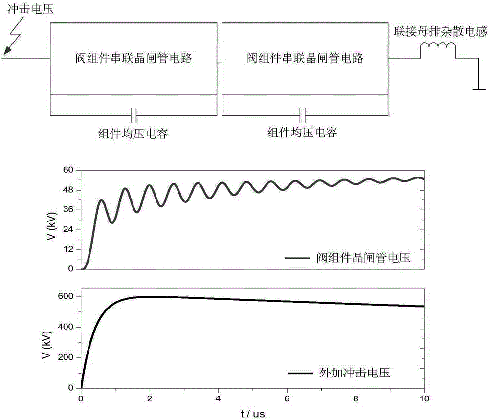
The invention provides a high-voltage DC transmission converter valve single-row valve tower which comprises a top shielding cover, a bottom shielding cover and a converter valve arranged between the top shielding cover and the bottom shielding cover, wherein the top shielding cover and the bottom shielding cover are arranged horizontally. The converter valve is connected with the top shielding cover and the bottom shielding cover through suspension insulators. The converter valve is formed by connecting converter valve modules, forming an inclination angle with the horizontal direction, in series in sequence in the vertical direction in the form of a zigzag rule. The high-voltage DC transmission converter valve single-row valve tower is more compact in overall structure and more reasonable in layout, and meanwhile, better solves the problems of high-frequency oscillation due to cooling water circuit insulation and connecting busbar inductance, reduces operational risks, and meets the design requirement for higher voltage and current level of the (ultra) high-voltage DC transmission converter valve.

Description

technical field [0001] The invention relates to a valve tower, in particular to a foldable single-row valve tower for a high-voltage direct current transmission converter valve. Background technique [0002] The increasing demand for electric energy in modern social and economic activities has promoted the continuous evolution of the structure and scale of the power system. At present, in order to adapt to the characteristics of high concentration of power load and energy distribution and the shortage of energy resources in heavy load areas, and to meet the requirements of environmental protection, large-scale clean energy centralized development and long-distance transmission have gradually become the mainstream energy development and utilization methods. DC transmission technology is widely adopted due to its economic advantages in long-distance transmission of electric energy and technical advantages in enhancing grid stability. [0003] The HVDC converter valve is the c...

Claims


Application Information

Patent Timeline
IPC IPC(8): H02M7/00H02J3/36
CPCH02M7/00Y02E60/60H05K7/14339
Inventor 高冲杨俊魏晓光刘杰
Owner GLOBAL ENERGY INTERCONNECTION RES INST CO LTD
Why Eureka
Try Eureka