Three-dimensional porous micro-fluidic chip and preparing method and application thereof

A microfluidic chip, three-dimensional porous technology, applied in the fields of biology, chemistry and material science, can solve the problems of high price, limited application, complex technology, etc., and achieve the effect of low cost, easy operation and good repeatability

Active Publication Date: 2016-01-20
WUHAN UNIV
View PDF5 Cites 8 Cited by
  • Summary
  • Abstract
  • Description
  • Claims
  • Application Information

AI Technical Summary

Problems solved by technology

However, most of the preparation steps of microfluidic chips are cumbersome, complica

Method used


Image

  • Three-dimensional porous micro-fluidic chip and preparing method and application thereof
  • Three-dimensional porous micro-fluidic chip and preparing method and application thereof
  • Three-dimensional porous micro-fluidic chip and preparing method and application thereof

Examples


Embodiment 1

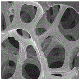
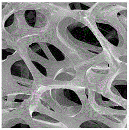
[0045] (1) The nickel foam (0.5mm×4mm×20mm) was ultrasonically cleaned with acetone, ethanol and ultrapure water for 30 minutes, and then dried in an oven. figure 1 A scanning electron micrograph of nickel foam, showing its three-dimensional porous structure.

[0046] (2) Immerse the dried nickel foam into a 2mL centrifuge tube filled with uncrosslinked PDMS (polydimethylsiloxane) liquid, and centrifuge at 8000rpm for 5 minutes to fully infiltrate the nickel foam with PDMS.

[0047] (3) Transfer the PDMS-impregnated nickel foam obtained in step (2) to an empty 2mL centrifuge tube, centrifuge at 3000rpm for 3 minutes to remove the PDMS in the pores of the nickel foam, and then heat in an oven at 80°C for 3 hours to solidify the PDMS.

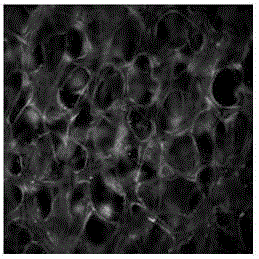
[0048] (4) Immerse the PDMS-coated nickel foam obtained in step (3) in a 7mol / L nitric acid solution, etch for 1 hour to remove the nickel template, and then wash off the residual nitric acid solution with ultrapure water to obtain a three-dimens...

Embodiment 2

[0057] (1) The nickel foam (1.2mm×4mm×20mm) was ultrasonically cleaned with acetone, ethanol and ultrapure water for 30 minutes, and then dried in an oven.

[0058] (2) Immerse the dried nickel foam into a 2mL centrifuge tube filled with uncrosslinked PDMS liquid, and centrifuge at 6000rpm for 3 minutes to fully infiltrate the nickel foam with PDMS.

[0059] (3) Transfer the PDMS-impregnated nickel foam obtained in step (2) to an empty 2mL centrifuge tube, centrifuge at 3000rpm for 3 minutes to remove excess PDMS in the pores of the nickel foam, and then heat in an oven at 75°C for 4 hours to solidify the PDMS.

[0060] (4) Immerse the PDMS-coated nickel foam obtained in step (3) in a 14mol / L nitric acid solution, etch for 5 hours to remove the nickel template, and then wash off the residual nitric acid solution with ultrapure water to obtain a three-dimensional porous material.

[0061] (5) Immediately immerse the obtained three-dimensional porous material Plasma in phosphat...


PUM


Abstract

The invention discloses a three-dimensional porous micro-fluidic chip and a preparing method and application thereof. Foam metal serves as a template, a micro-fluidic chip material is used for copying the structure of the template integrally, and the metal template is removed to obtain a three-dimensional porous material; the three-dimensional porous material is modified in a silanized mode, pores are filled with temperature sensing materials, and after being integrated with the micro-fluidic chip, the temperature sensing materials are removed to obtain the three-dimensional porous micro-fluidic chip; functional groups of the surface of the three-dimensional porous material are activated and coupled with biomolecules to obtain the three-dimensional porous micro-fluidic detection chip. The three-dimensional porous micro-fluidic chip can be applied to biomedicine analysis and used for separating circulating tumor cells; the three-dimensional porous micro-fluidic chip has the advantages of having porosity, and being high in transparency and toughness and good in biocompatibility; the three-dimensional porous structure can fix a large number of biomolecules, and materials to be detected can be separated with high efficiency and high throughput. Preparation of the three-dimensional porous micro-fluidic chip is easy and easy to implement, and the chip is low in cost and good in repeatability.

Description

technical field [0001] The invention belongs to the fields of biology, chemistry and material science, and specifically relates to a three-dimensional porous microfluidic chip and its preparation method and application. Background technique [0002] Circulating tumor cells are tumor cells shed from cancer lesions and enter peripheral blood. The detection of circulating tumor cells is of great significance for early diagnosis of tumors, evaluation of personalized treatment, drug evaluation and surgical prognosis. Due to the extremely small number of circulating tumor cells in the blood, their isolation poses a great challenge. At present, it is urgent to develop a new method for isolating circulating tumor cells that is simple, efficient and rapid. [0003] Microfluidic chip is a technology that has developed rapidly in recent years. It has the advantages of easy integration, fast analysis speed, high throughput, and safety. It is used in tumor marker detection, tumor cell s...

Claims


Application Information

Patent Timeline
IPC IPC(8): C12M1/34C12Q1/02
CPCC12Q1/02
Inventor 黄卫华程世博谢敏徐加泉胡艺凡
Owner WUHAN UNIV
Why Eureka
Try Eureka