Capacitive concentration difference power generation technology

A capacitive and capacitor electrode technology, applied in the field of capacitive concentration difference power generation, can solve the problems of high production cost of membrane, easy to be corroded, and large device, and achieve the effects of low cost, simple device and small device area.

Active Publication Date: 2016-03-23
DALIAN UNIV OF TECH
View PDF3 Cites 9 Cited by
  • Summary
  • Abstract
  • Description
  • Claims
  • Application Information

AI Technical Summary

Problems solved by technology

Osmotic pressure technology, huge device, high cost and low efficiency
Reverse electrodialysis technology requires a lot

Method used


Image

  • Capacitive concentration difference power generation technology
  • Capacitive concentration difference power generation technology

Examples


Embodiment 1

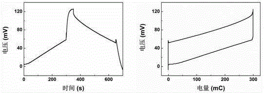
[0039] Example 1: Electric double layer capacitive concentration difference power generation technology

[0040] The electric double layer type electrochemical capacitor is used in this embodiment, that is, the ion storage mechanism is the adsorption and desorption of the electric double layer.

[0041] The capacitor is composed of a current collector, a positive electrode, a diaphragm and a negative electrode; the current collector is made of conductive graphite paper; the diaphragm is a layer of non-woven fabric. Electrolyte is sodium chloride aqueous solution, concentration is 1g / L and 30g / L respectively. Both the positive and negative electrodes are made of YP50 activated carbon (Kuraray Chemical Co., LTD, Japan), with a specific surface area of ​​1600m 2 / g.

[0042] YP50 activated carbon, conductive carbon black, and binder are mixed in a ball mill at a mass ratio of 8:1:1. The solvent is N-methylpyrrolidone (NMP), and the mass percentage of YP50 activated carbon is ...

Embodiment 2

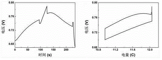
[0051] Example 2: Hybrid Capacitive Concentration Power Generation Technology

[0052] In this embodiment, a hybrid electrochemical capacitor is used, that is, the positive and negative electrodes have different ion storage mechanisms, the positive electrode is a Faraday reaction mechanism, and the negative electrode is an electric double layer adsorption mechanism.

[0053] The capacitor is composed of a current collector, a positive electrode, a diaphragm and a negative electrode; the current collector is made of conductive graphite paper; the diaphragm is a layer of non-woven fabric. The electrolyte is sodium chloride aqueous solution, dilute brine and concentrated brine with concentration of 1g / L and 30g / L respectively.

[0054] In the present embodiment, the positive electrode material selects sodium manganese oxide Na 4 mn 9 o 18 The negative electrode material is YP50 activated carbon (Japan Kuraray Chemical Co., LTD), with a specific surface area of ​​1600m 2 / g....


PUM

PropertyMeasurementUnit
Specific surface areaaaaaaaaaaa
Thicknessaaaaaaaaaa
Power densityaaaaaaaaaa

Abstract

A capacitive concentration difference power generation technology belongs to the capacitor application and concentration difference energy utilization field. An electrochemical capacitor is formed by positive and negative electrodes, diaphragm, a current collector and an electrolyte. Positive and negative electrode materials comprise an adsorbed electrode depending on high specific surface area adsorption ions, a reaction electrode depending on redox reaction storage ions and the like. The electrolyte comprises a plurality of fluids with different concentrations, such as high strong brine and low strong brine, seawater and fresh water, high strong CO2 and low strong CO2 and the like. The capacitor realizes an energy cycle similar to a Carnot cycle through four steps of ''charging-open circuit-discharging-open circuit''. A concentration difference in the electrolyte is converted into electric energy. Compared to a concentration difference energy utilization technology of pressure penetration, reverse electro dialysis and the like, by using the technology in the invention, cost is low, an apparatus is simple, energy efficiency is high and an application scope is wide.

Description

technical field [0001] The invention relates to a capacitive concentration difference power generation technology, which belongs to the fields of capacitor application and concentration difference energy utilization. Background technique [0002] A capacitor is a device that holds electrical charge. A capacitor is composed of two metal electrodes with an insulating dielectric in between. When a voltage is applied between two metal electrodes, charges are stored on the electrodes, so capacitors are energy storage elements. The capacitance of traditional capacitors is small, only on the order of microfarads or millifarads. [0003] The capacitance of electrochemical capacitors (often called supercapacitors) can reach the order of farads or even thousands of farads. It is a new type of energy storage device with high power density, short charging time, long service life, energy saving and environmental protection. There are two main energy storage mechanisms, electric double...

Claims


Application Information

Patent Timeline
IPC IPC(8): H01G11/84H01G11/58
CPCY02E60/13H01G11/84H01G11/58
Inventor 邱介山詹菲王刚
Owner DALIAN UNIV OF TECH
Why Eureka
Try Eureka