Ablation catheter
A technology for ablation catheters and catheters, which is applied in the direction of heating surgical instruments, measuring devices, instruments, etc., can solve the problems of high packaging difficulty, complicated preparation process, and high price, and achieve the effect of less external interference and simple manufacturing process
- Summary
- Abstract
- Description
- Claims
- Application Information
AI Technical Summary
Problems solved by technology
Method used
Image
Examples
Embodiment 1
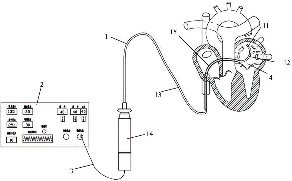
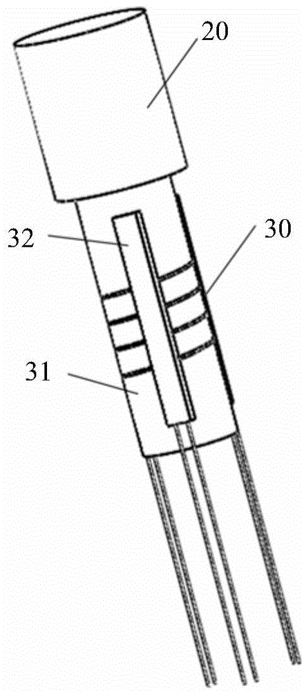
[0055] figure 1 It is a schematic diagram of heart ablation performed by the ablation catheter in the embodiment of the present invention. figure 2 It is a structural schematic diagram of the distal end of the ablation catheter in which the annular elastic body is a helically cut metal tube in an embodiment of the present invention.
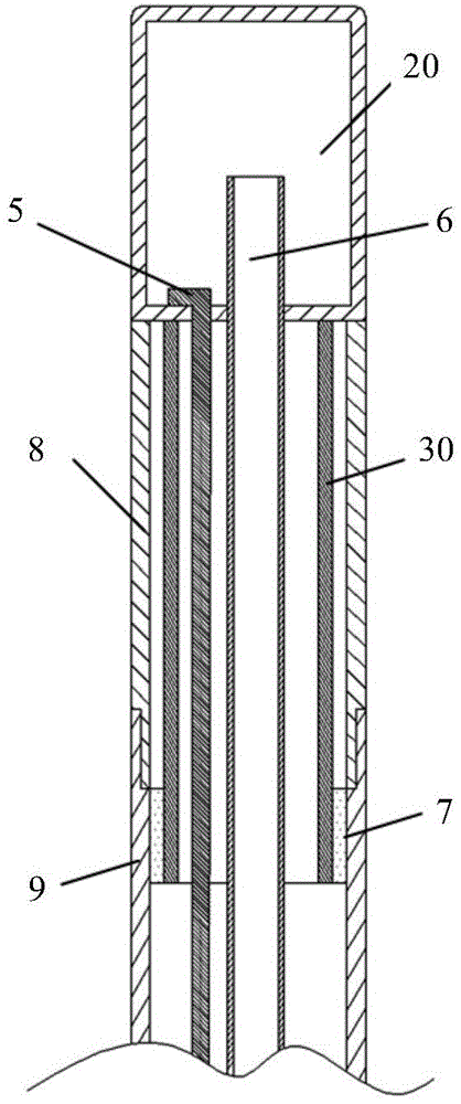
[0056] See figure 1 and figure 2 , the ablation catheter 1 passes through the puncture sheath 15 and enters the heart through the inferior vena cava to perform ablation. The ablation catheter provided by the embodiment of the present invention includes a catheter distal end 11 , a deflectable section 12 , a catheter main body 13 and a control handle 14 connected in sequence. The distal end 11 of the catheter is equipped with an ablation electrode 20, which can apply energy for ablation. The material of the ablation electrode 20 is metal, which can be stainless steel, gold or platinum-iridium alloy. The control handle 14 can control the defl...
Embodiment 2
[0065] FIG. 4( a ) is a schematic structural view of the distal end of the ablation catheter in Embodiment 2 of the present invention, and FIG. 4( b ) is a schematic cross-sectional view of the distal end of the ablation catheter in Embodiment 2 of the present invention.
[0066] Please refer to Fig. 4 (a) and Fig. 4 (b), the annular elastic body 41 of pressure sensor 40 is made of cutting metal tube 43 and the sleeve tube 44 that is coated on described cutting metal tube 43, and sleeve tube 44 is plastic Or rubber tube, its material can be PVC, PU or silicone rubber, and plastic or rubber tube is connected with cutting metal tube 43 by epoxy resin glue or other adhesives. Afterwards, the strain gauge 42 is adhered to the outer surface of the casing 44 along the circumferential direction by epoxy glue or other adhesives. In order to clearly show each structure, a certain gap is drawn between the cutting metal pipe 43 and the sleeve 44 , but in fact, there is no gap between the...
Embodiment 3
[0068] Figure 5 It is a structural schematic diagram in Embodiment 3 of the present invention.
[0069] See Figure 5 , the annular elastic body 51 body includes an upper end 52, a connecting section 53 and a lower end 54, the upper end 52 and the lower end 54 are annular structures with the same diameter, the connecting section 53 is an "N" type rod, and the upper end 52 and the lower end 54 pass through the "N" "Type bar is connected, so that the annular elastic body 51 can move up and down, left and right, one end of the strain gauge (not shown in the figure) is connected to the upper end 52, and the other end is connected to the lower end 54. Of course, in other embodiments, the connecting section 53 can also be other types of curved rods such as "S" type or "M" type, and the present invention is not limited to this.
PUM
| Property | Measurement | Unit |
|---|---|---|
| Pitch | aaaaa | aaaaa |
| Width | aaaaa | aaaaa |
| Length | aaaaa | aaaaa |
Abstract
Description
Claims
Application Information
 - R&D
- Intellectual Property
- Life Sciences
- Materials
- Tech Scout
- Unparalleled Data Quality
- Higher Quality Content
- 60% Fewer Hallucinations
Browse by: Latest US Patents, China's latest patents, Technical Efficacy Thesaurus, Application Domain, Technology Topic, Popular Technical Reports.
© 2025 PatSnap. All rights reserved.Legal|Privacy policy|Modern Slavery Act Transparency Statement|Sitemap|About US| Contact US: help@patsnap.com


