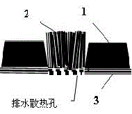
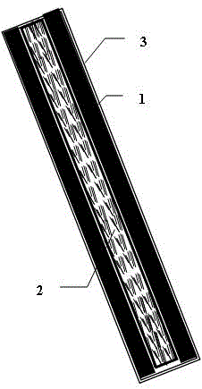
Pantograph pan with flexible electric brush
A technology of pantograph slides and flexible electricity, which is applied in the direction of current collectors, electric vehicles, power collectors, etc., can solve the problems that the number of conductive spots cannot be effectively increased, the effect is not very satisfactory, and the contact resistance fluctuates, so as to reduce electric heating. The risk of erosion, reducing the occurrence of arcs, and reducing the effect of electrical wear
- Summary
- Abstract
- Description
- Claims
- Application Information
AI Technical Summary
Problems solved by technology
Method used
Image

Examples
Embodiment 1
[0023] Example one, pantograph skateboard with copper brush
[0024] Step 1. Combine the large-tow carbon fiber and its graphitized graphite fiber with copper metal fiber and aramid fiber into a bundle according to a certain proportion, and then cut into a suitable length; the proportion of carbon fiber is not less than 5%, and the proportion of copper fiber The ratio is not less than 10%, and the ratio of aramid fiber is not less than 5%; the height of the fiber bundle is at least 10mm higher than the height of the rigid conductive panel,
[0025] Step 2. Fix the above conductive fibers in the cut copper wire mesh holes, glue them firmly with conductive adhesive, and solidify them to make a flexible brush with suitable density;
[0026] Step 3: Stick a strip of copper-impregnated carbon plate with conductive adhesive on the front end of the aluminum alloy substrate that has been decontaminated and frosted, and press it firmly;
[0027] Step 4, stick the copper brush with conductive g...
Embodiment 2
[0030] Example two, pantograph slide plate with stainless steel brush
[0031] Step 1. Combine large-tow carbon fiber and its graphitized graphite fiber with stainless steel fiber and aramid fiber in a certain proportion into bundles, and then cut into a suitable length; the proportion of carbon fiber is not less than 15%, and the proportion of stainless steel fiber Not less than 30%, the proportion of aramid fiber is not less than 10%; the height of the fiber bundle is at least 15mm higher than the height of the rigid conductive panel,
[0032] Step 2, fix the above conductive fiber in the mesh of the cut stainless steel wire mesh, glue it firmly with conductive glue, and solidify to make a flexible brush with appropriate density;
[0033] Step 3, stick a piece of graphite board with conductive adhesive to the front end of the aluminum alloy substrate that has been decontaminated and frosted, and press it firmly;
[0034] Step 4. Stick the stainless steel brush with conductive glue i...
Embodiment 3
[0037] Example three, pantograph slide plate with nickel brush
[0038] Step 1. Combine large-tow carbon fibers and graphitized graphite fibers with nickel fibers and aramid fibers in a certain proportion into bundles, and then cut them to a suitable length; the proportion of carbon fiber is not less than 20%, and the proportion of nickel fiber Not less than 40%, the proportion of aramid fiber is not less than 15%; the height of the fiber bundle is at least 25mm higher than the height of the rigid conductive panel,
[0039] Step 2. Fix the above conductive fiber in the mesh of the cut nickel wire mesh, stick it firmly with conductive glue, and cure it to make a flexible brush with suitable density;
[0040] Step 3: Stick a strip of copper-impregnated carbon plate with conductive adhesive on the front end of the aluminum alloy substrate that has been decontaminated and frosted, and press it firmly;
[0041] Step 4, stick the nickel brush in the middle of the aluminum alloy substrate wi...
PUM
 Abstract
Description
Claims
Application Information
 - R&D
- Intellectual Property
- Life Sciences
- Materials
- Tech Scout
- Unparalleled Data Quality
- Higher Quality Content
- 60% Fewer Hallucinations
Browse by: Latest US Patents, China's latest patents, Technical Efficacy Thesaurus, Application Domain, Technology Topic, Popular Technical Reports.
© 2025 PatSnap. All rights reserved.Legal|Privacy policy|Modern Slavery Act Transparency Statement|Sitemap|About US| Contact US: help@patsnap.com