
A Hybrid Integrated Electronically Controlled Liquid Crystal Optical Switch Array

An optical switch array and integrated circuit technology, applied in the field of optical communication, can solve the problems of unsatisfactory insertion loss, large insertion loss and high cost, and achieve flexible and diverse electronic control methods, good structural adaptability, and polarization adaptability. Good results

Active Publication Date: 2018-12-28
HUAZHONG UNIV OF SCI & TECH
View PDF6 Cites 0 Cited by
  • Summary
  • Abstract
  • Description
  • Claims
  • Application Information

AI Technical Summary

Problems solved by technology

[0003] To sum up, the existing mainstream optical switch technology still has defects in dealing with the current high-intensity big data transmission beams, mainly in the following aspects: (1) The millisecond-level switching time of mechanical optical switches is too long, and insertion The loss is still large and the isolation is insufficient; (2) MEMS optical switches need to adjust the beam transmission through the mechanical movement of the micro-functional structure, and the switching action caused by the mechanical movement inertia is relatively slow, the cycle is long, and the insertion loss is still not ideal (3) Conventional electro-optic switches generally use the electro-optic or electro-absorption effect of materials to change their refractive index, beam phase or polarization state under the action of an electric field, based on optical interference, diffraction or polarization, etc. Changing the light intensity or bending the optical path, the modulation and curing of the optical structure and parameters are complicated, the control is relatively difficult, and the parameters of different types of switches are uneven, it is difficult to make overall plans and the cost is high; (4) Directional coupling optical switches Generally, the periodic conversion of optical power is realized by coupling waveguides, such as typical M-Z interferometric and waveguide M-Z interferometric optical switches, which have complex structures and configurations, many control and variable factors, and cost problems; (5) Polarization Modulated optical switches are mainly aimed at transmission wave fields with high polarization degrees, including conventional liquid crystal polarized light switches, etc.; (6) Typical thermo-optical switches are based on the temperature dependence of the physical properties of the medium caused by thermal effects, so that the refractive index of the transmission medium changes And delayed optical phase, with large thermal inertia, often used in steady state or slowly changing occasions; (7) Typical acousto-optic switches are based on the mechanical strain of the acoustic wave in the material to cause periodic changes in the refractive index to form a Bragg grating to diffract Specific wavelength beams, mainly used for beam on-off operation at long wavelengths due to the low-frequency characteristics of acoustic waves

Method used


Image

  • A Hybrid Integrated Electronically Controlled Liquid Crystal Optical Switch Array
  • A Hybrid Integrated Electronically Controlled Liquid Crystal Optical Switch Array
  • A Hybrid Integrated Electronically Controlled Liquid Crystal Optical Switch Array

Examples


Embodiment Construction

[0025] In order to make the object, technical solution and advantages of the present invention clearer, the present invention will be further described in detail below in conjunction with the accompanying drawings and embodiments. It should be understood that the specific embodiments described here are only used to explain the present invention, not to limit the present invention. In addition, the technical features involved in the various embodiments of the present invention described below can be combined with each other as long as they do not constitute a conflict with each other.

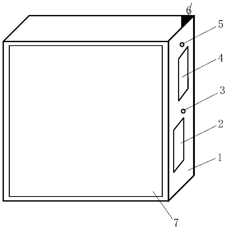
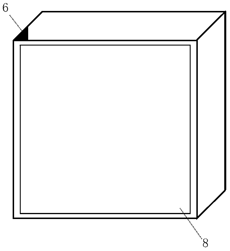
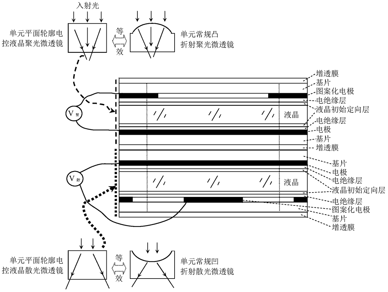
[0026] figure 1 It is a schematic diagram of the front (light incident surface) structure of a hybrid integrated electronically controlled liquid crystal optical switch array according to an embodiment of the present invention, figure 2 It is a structural schematic diagram of the back (light exit surface) of a hybrid integrated electronically controlled liquid crystal light switch array accord...


PUM


Abstract

The invention discloses a hybrid integrated electric-control liquid-crystal optical switch array. The hybrid integrated electric-control liquid-crystal optical switch array comprises a hybrid integrated electric-control liquid-crystal optically-focused microlens array and an electric-control liquid-crystal optically-diffused microlens array, and the optical axis of each liquid-crystal optically-focused microlens unit is coincident with that of each liquid-crystal optically-diffused microlens unit. When being powered up, optically-focused microlenses carry out internal-focusing optically-focused operations to a light beam under the effect of electric-control signals of different mean square amplitudes. and optically-diffused microlenses carry out controllable operations with a controllable diffusion degree to a light beam under the effect of electric-control signals of different mean square amplitudes. When being powered off, the liquid-crystal optically-focused microlenses and the optically-diffused microlenses are converted into liquid-crystal phase-shift plates which only delay light wave phases, and the liquid-crystal phase-shift plates which are formed after the liquid-crystal optically-focused microlenses and the optically-diffused microlenses are powered off form the opening state of the optical switch. The hybrid integrated electric-control liquid-crystal optical switch array can complete electric-control light beam on-off operations, and is suitable for optical fiber or optical cable systems which are wide in spectrum scope and large in wave beam intensity change scope.

Description

technical field [0001] The invention belongs to the technical field of optical communication, and more specifically relates to a hybrid integrated electronically controlled liquid crystal optical switch array. Background technique [0002] At present, the widely used optical fiber communication technology uses light as the information carrier and optical fiber as the transmission medium, and transmits voice, image and data information by transmitting light wave signals in the optical fiber. With the characteristics of large transmission capacity and good confidentiality, it has become the most important means of wired communication in the world. The optical switch is an important functional component in the optical fiber communication system. It has one or more optional transmission windows and channels. The optical signals in the path perform mutual switching operations. So far, optical switches have become the basic functional components in optical transmission and optic...

Claims


Application Information

Patent Timeline
Patent Type & Authority Patents(China)
IPC IPC(8): G02F1/13G02F1/133G02F1/1333
CPCG02F1/1313G02F1/13306G02F1/1333
Inventor 张新宇樊迪雷宇信钊炜魏冬桑红石王海卫谢长生
Owner HUAZHONG UNIV OF SCI & TECH
Learn More