Sewage composite catalytic oxidation treatment method

A technology of catalytic oxidation and treatment method, applied in water/sewage treatment, light water/sewage treatment, oxidized water/sewage treatment, etc., can solve the problems of high energy consumption, low degradation efficiency, large secondary pollution, etc. Low consumption, high oxidation potential and small secondary pollution

Active Publication Date: 2016-05-04
ZHEJIANG UNIVERSITY OF SCIENCE AND TECHNOLOGY
View PDF9 Cites 5 Cited by
  • Summary
  • Abstract
  • Description
  • Claims
  • Application Information

AI Technical Summary

Problems solved by technology

[0008] Aiming at a series of problems such as low degradation efficiency, high energy consumption, large secondary pollution and inability to deal with large fluctuations in sewage index in the prior art of sewage catalytic oxidation treatment, the present invention provides a sewage composite catalytic oxidation treatment method

Method used


Image

  • Sewage composite catalytic oxidation treatment method

Examples


Embodiment 1

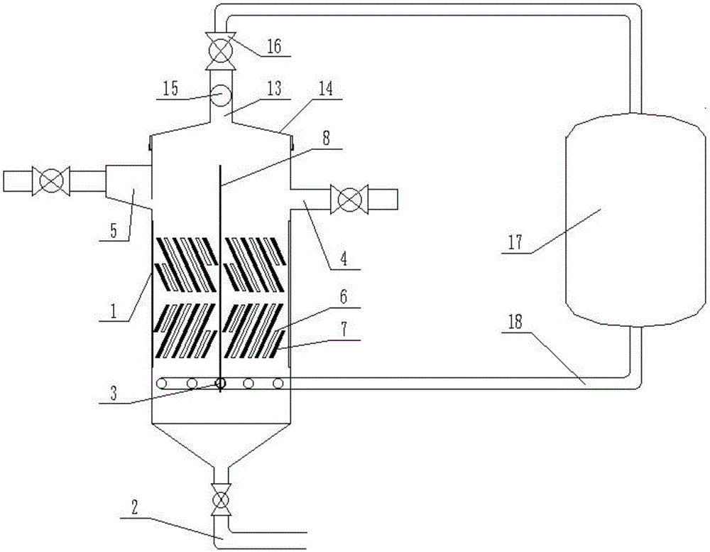
[0028] Such as figure 1 As shown, it is a structural schematic diagram of the catalytic oxidation device adopted in the present invention, including a device body 1, a solid phase outlet 2 and a gas phase inlet 3 are provided at the bottom of the device body 1, a liquid phase inlet 4 is provided on the right side of the device body 1 top, and a liquid phase inlet 4 is provided on the left side of the device body 1. A liquid phase outlet 5 is provided on the side, and a baffle plate 8 parallel to the axial direction of the device body 1 is provided in the device body 1. Both sides of the baffle plate 8 include four light source plates 6 and five catalyst plates 7, The light source plate 6 and the catalyst plate 7 are arranged adjacent to each other in parallel, and form an angle of 40° with the axial direction of the device body 1 . The light source plate 6 is provided with a light source, and the light source includes a visible light source and an ultraviolet light source. The...

Embodiment 2

[0033] Embodiment 2 is identical with embodiment 1, and difference is that device internal pressure is 0.1Mpa, and the ratio of ozone inlet and sewage flow is 1:1; The ratio of the hydraulic retention time of ozone and the hydraulic retention time of sewage is 3: 1. Both sides of the deflection baffle 8 include two light source plates 6 and two catalyst plates 7 adjacent to each other and arranged in parallel in sequence, and the axial direction of the light source plate 6 and catalyst plate 7 and the device body 1 are both clamped at 65° Angle, the specific arrangement sequence is: ultraviolet light source plate, catalyst plate, visible light source plate, catalyst plate; the catalyst plate is filled with catalyst particles, and the catalyst is a mixture of nickel and iron.

Embodiment 3

[0035] Embodiment 3 is identical with embodiment 1, and difference is that device internal pressure is 0.3Mpa, and the ratio of ozone feed rate and sewage flow is 5:1, and the ratio of the hydraulic retention time of ozone and the hydraulic retention time of sewage is 0.5: 1. Both sides of the deflection baffle 8 include four light source plates 6 and three catalyst plates 7 that are adjacent to each other and arranged in parallel. Angle, the specific order of arrangement is: visible light source plate, catalyst plate, ultraviolet light source plate, catalyst plate, visible light source plate, catalyst plate, ultraviolet light source plate; the surface of the catalyst plate is electroplated with a catalyst, and the catalyst is zinc.


PUM


Abstract

The present invention relates to the field of sewage treatment, and discloses a sewage composite catalytic oxidation treatment method comprising the simultaneous steps of catalyst catalytic oxidation, photocatalytic oxidation and ozone oxidation, in the catalyst catalytic oxidation step, sewage is introduced into a catalytic oxidation device filled with a catalyst, the catalyst is an element or oxide of titanium, copper, zinc, iron, nickel or manganese and a mixture thereof; in the photocatalytic oxidation step, visible light and ultraviolet light are simultaneously used for irradiation of to-be-treated sewage; in the ozone oxidation step, ozone is introduced into the catalytic oxidation device, and the ratio of ozone fed amount to sewage flow is 1 to 5: 1. The sewage composite catalytic oxidation treatment method uses composite catalytic oxidation method for treatment of the sewage, and has the advantages of high efficiency, low energy consumption, low secondary pollution, adaptation to water quality, concentration and component fluctuations, and the like.

Description

technical field [0001] The invention relates to the field of wastewater treatment, in particular to a wastewater composite catalytic oxidation treatment method. Background technique [0002] With the change of production technology and the complexity of application requirements, the composition, concentration, chromaticity, odor and toxicity of pollutants in the wastewater produced by various industries will change to a very large extent, and the complexity of water quality is very high. . In such a large environment, it is conceivable that it is difficult for any single sewage treatment method to be universally promoted. From the perspective of the development of modern water treatment technology, composite treatment methods are an inevitable development trend. The difference lies in the combination of processes and their characteristic parameters for different water quality wastewater. For different types of wastewater, in order to avoid secondary pollution to the enviro...

Claims


Application Information

Patent Timeline
Patent Type & Authority Applications(China)
IPC IPC(8): C02F1/30C02F1/32C02F1/78
CPCC02F1/30C02F1/32C02F1/725C02F1/78C02F2305/10
Inventor 朱文芳宋亚丽王小华
Owner ZHEJIANG UNIVERSITY OF SCIENCE AND TECHNOLOGY
Why Eureka
Try Eureka