
Manufacturing method of power transistor

A technology for power transistors and manufacturing methods, applied in semiconductor/solid-state device manufacturing, electrical components, circuits, etc., can solve problems such as increased manufacturing costs, poor performance at room temperature and high temperature reliability, and easy hardening of photoresists, achieving The effect of improving yield and reliability, shortening production cycle, and reducing the number of photolithography times

Active Publication Date: 2018-09-04
深圳深爱半导体股份有限公司
View PDF4 Cites 0 Cited by
  • Summary
  • Abstract
  • Description
  • Claims
  • Application Information

AI Technical Summary

Problems solved by technology

[0004] However, N+ implantation uses N+ photoresist as a mask, which requires an additional photolithography process, which includes process steps such as gluing, gluing, alignment, exposure, development, and development inspection, which increases manufacturing costs and also Increases the time required for manufacturing, making manufacturing slow and inefficient
[0005] On the other hand, N+ implantation uses N+ photoresist as a mask. After N+ implantation, the photoresist tends to harden and is more tightly bonded to the silicon wafer, making it difficult to remove the photoresist.
When the glue is not cleaned, the residual glue will melt in the subsequent high-temperature process and pollute the surface of the semiconductor device, which will reduce the breakdown voltage of the device, increase the leakage, and deteriorate the normal temperature performance and high temperature reliability.
Glue filaments are sometimes difficult to detect by microscopy and are easy to miss
Even if the glue filament is detected, its rework process will increase the manufacturing cost and prolong the chip manufacturing cycle

Method used

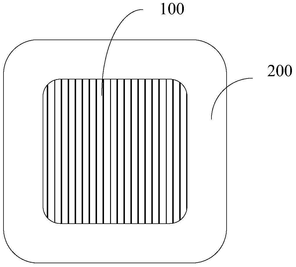
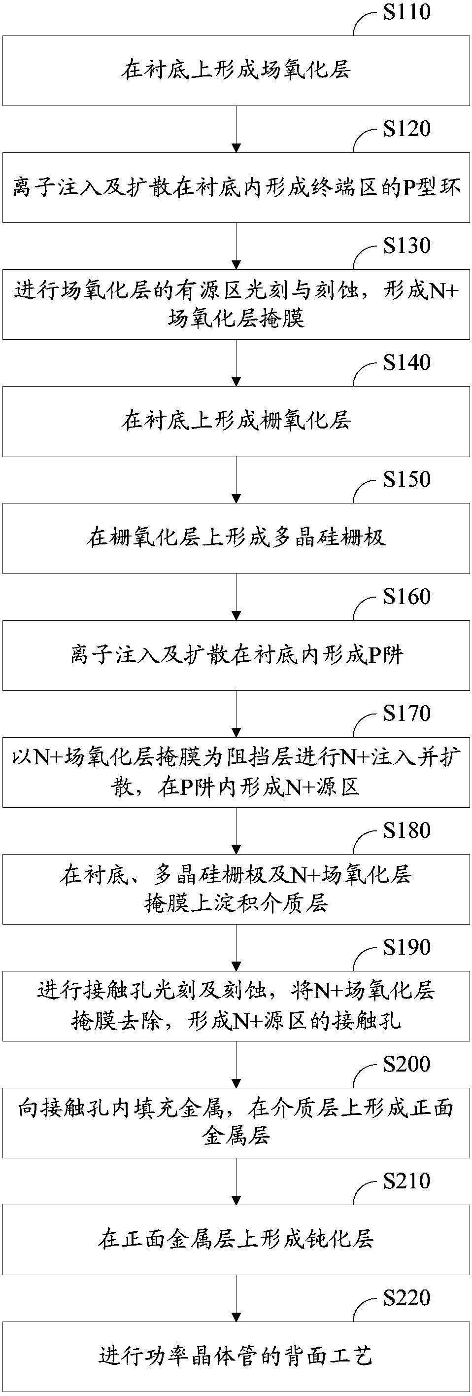
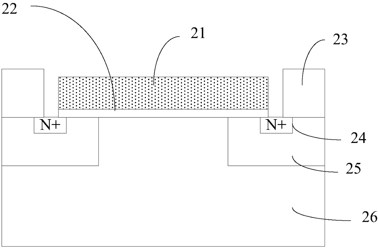

Image

  • Manufacturing method of power transistor
  • Manufacturing method of power transistor
  • Manufacturing method of power transistor

Examples


Embodiment Construction

[0024] In order to facilitate the understanding of the present invention, the present invention will be described more fully below with reference to the associated drawings. A preferred embodiment of the invention is shown in the drawings. However, the present invention can be embodied in many different forms and is not limited to the embodiments described herein. Rather, these embodiments are provided so that the disclosure of the present invention will be thorough and complete.

[0025] Unless otherwise defined, all technical and scientific terms used herein have the same meaning as commonly understood by one of ordinary skill in the technical field of the invention. The terms used herein in the description of the present invention are for the purpose of describing specific embodiments only, and are not intended to limit the present invention. As used herein, the term "and / or" includes any and all combinations of one or more of the associated listed items.

[0026] The se...


PUM


Abstract

The invention relates to a manufacturing method for a power transistor. The manufacturing method comprises the steps of forming a field oxide layer on a substrate; forming a P type field limiting ring in a terminal region through ion implantation; performing photoetching and etching on an active region of the field oxide layer to form an N+ field oxide layer mask; forming a gate oxide layer; forming a polysilicon gate; forming a P well; taking the N+ field oxide layer mask as a barrier layer for performing N+ injection and dispersion to form an N+ source region in the P well; depositing a dielectric layer; performing photoetching and etching on a contact hole, removing the N+ field oxide layer mask to form the contact hole in the N+ source region; forming a front surface metal layer; forming a passivating layer; and performing a back surface process for the power transistor. According to the manufacturing method for the power transistor, the etching times are reduced, so that the production cost of the device is lowered, the production period of the device is shortened, and the production efficiency is improved; and in addition, the problem of surface contamination of the semiconductor possibly caused by residual photoresist of an N+ photoresist mask in the conventional manufacturing is solved, and the yield and reliability of the product are improved.

Description

technical field [0001] The invention relates to the field of semiconductor manufacturing, in particular to a method for manufacturing a power transistor. Background technique [0002] The market for power semiconductor devices such as VDMOS and IGBT is huge. In today's increasingly fierce competition in the production and sales of power semiconductor devices, power semiconductor device design companies and manufacturers are facing tremendous pressure to produce high-performance devices and reduce production costs. [0003] Cells in the active region of power semiconductor devices usually include three types of ion implantation: P well implantation, N+ implantation and P+ implantation. Wherein, the P well implantation is generally a small dose of boron implantation (P-implantation), the N+ implantation is usually a large dose of arsenic (or phosphorus) implantation, and the P+ implantation is usually a large dose of boron implantation. And generally, the dose of N+ implanta...

Claims


Application Information

Patent Timeline
Patent Type & Authority Patents(China)
IPC IPC(8): H01L21/027H01L21/266
CPCH01L21/0332H01L21/266
Inventor 李学会
Owner 深圳深爱半导体股份有限公司
Learn More