Embedded ultrasonic motor drive controller

A drive controller, ultrasonic motor technology, applied in the direction of generator/motor, piezoelectric effect/electrostrictive or magnetostrictive motor, electrical components, etc., can solve the problem of poor matching effect, low control accuracy, driving mode and Control strategy description is less and other problems, to achieve the effect of improving versatility, optimizing control parameters, and facilitating human-computer interaction

Active Publication Date: 2016-10-12
NANJING UNIV OF AERONAUTICS & ASTRONAUTICS
View PDF7 Cites 7 Cited by
  • Summary
  • Abstract
  • Description
  • Claims
  • Application Information

AI Technical Summary

Problems solved by technology

The patent number is ZL200710134453.3, and the invention patent named "ultrasonic motor drive controller based on embedded system level chip" discloses an ultrasonic motor driver, including a manual encoder adjustment circuit, a PSoC chip, a push-pull inverter circuit, a Voltage circuit, inductance matching circuit, etc. The advantage of the ultrasonic motor drive controller is that the structure is simple, and the frequency tracking of the ultrasonic motor is realized by using the lone pole feedback method, and the purpose of stabilizing the motor speed is achieved, but the control accuracy is low and the matching effect is low. Poor and low energy conversion efficiency
The patent number is ZL201210451717.9, and the invention patent titled "A Dual PWM Power Drive Topology for Ultrasonic Motors" discloses a dual PWM power drive topology for ultrasonic motors. The technical solution uses constant current power supply and power coupling components, which can It is convenient to adjust the driving frequency and voltage, and improves the energy conversion efficiency of the driver, but the ease of use is poor, and there are few descriptions on the driving method and control strategy

Method used


Image

  • Embedded ultrasonic motor drive controller
  • Embedded ultrasonic motor drive controller
  • Embedded ultrasonic motor drive controller

Examples


Embodiment Construction

[0019] The present invention is described in detail below in conjunction with accompanying drawing:

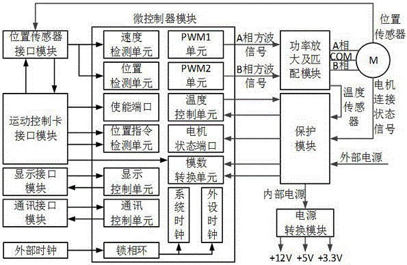
[0020] Such as figure 1As shown, the embedded ultrasonic motor drive controller in this embodiment includes an external clock, a microcontroller module, a power amplification and matching module, a position sensor interface module, a motion control card interface module, a protection module, a display interface module, and a communication interface module and power conversion modules. The external clock is generated by an oscillator composed of a crystal / ceramic resonator, and provides a clock signal for the system clock and the peripheral clock in the microcontroller module after being frequency multiplied by the phase-locked loop in the microcontroller module. The clock signal provides a time reference for the PWM1 unit and the PWM2 unit in the microcontroller module. The PWM1 unit generates an A-phase square wave signal and generates an A-phase drive signal through the pow...


PUM


Abstract

The invention discloses an embedded ultrasonic motor drive controller, and the controller comprises an external clock, a microcontroller module, a power amplification and matching module, a position sensor interface module, a motion control card interface module, a circuit protection module, a display interface module, a communication interface module and a power conversion unit module, wherein the external clock provides a time reference for the microcontroller module. A signal generated by the microcontroller module is used for driving a to-be-controlled ultrasonic motor. The position sensor interface module collects position information, and feeds back the position information to the microcontroller module. The motion control card interface module supplies an enabling signal, a position instruction signal and a speed instruction signal to the microcontroller module. The circuit protection module provides a function of motor connection protection and functions of overheating, overvoltage, undervoltage and overcurrent protection. The display interface module and the communication module provide man-machine interaction windows for a drive controller. The drive controller is good in universality, is diversified in control parameters, is easy for the integration of a plurality of control modes, and facilitates the implement of high-precision control of an ultrasonic motor.

Description

technical field [0001] The invention relates to an ultrasonic motor drive controller, which belongs to the field of motor drive control. Background technique [0002] Ultrasonic motor is a new type of micro motor. Its structure and operating principle are different from traditional electromagnetic motors. The ultrasonic motor mainly uses the inverse piezoelectric effect of the piezoelectric material to excite a kind of ultrasonic vibration of the elastic body, and through the friction between the stator and the rotor, the submicron deformation of the elastic body is converted into the rotary or linear motion of the mover. It has the advantages of low speed, large torque / mass ratio, fast response, self-locking when power is off, and no electromagnetic interference. It can meet many new requirements of modern automation equipment for motion devices, and has broad application prospects in the fields of biomedicine, semiconductor packaging, weaponry and aerospace. [0003] The...

Claims


Application Information

Patent Timeline
Patent Type & Authority Applications(China)
IPC IPC(8): H02N2/00
CPCH02N2/001
Inventor 时运来张军冯森娄成树赵淳生
Owner NANJING UNIV OF AERONAUTICS & ASTRONAUTICS
Why Eureka
Try Eureka