
Tubular composite shielded and insulated bus and making process thereof

A composite shielding and insulating busbar technology, applied in the direction of insulating conductors, insulating cables, insulating conductors/cables, etc., can solve problems such as the incompatibility of humidity and temperature, the decrease of electrical insulation performance of tube and busbar, and the increase of skin effect coefficient, etc. Achieve the effect of improving power supply reliability, good heat dissipation conditions, and low skin effect

Inactive Publication Date: 2016-10-26
JIANGSU PENGZHENG MECHANICAL & ELECTRICAL EQUIP
View PDF4 Cites 0 Cited by
  • Summary
  • Abstract
  • Description
  • Claims
  • Application Information

AI Technical Summary

Problems solved by technology

[0003] With the continuous development of the domestic economy, the power load of each substation has increased sharply, the operating current of the system has become larger and larger, the load has become more and more concentrated, and the capacity of the main transformer of the substation has also increased. The connection method of multi-piece rectangular busbars or direct cable connection is no longer suitable for the working method of large current (above 3000A), and at the same time, it causes large additional loss, uneven current distribution, and increased skin effect coefficient resulting in current carrying Phenomena such as capacity decline and contact heating are becoming more and more obvious
This technology was first applied to foreign projects by foreign companies, such as Swiss MGC company, German bpb company, etc., and was later introduced in China. However, the product structure of foreign companies and domestic companies is quite different. The busbars of foreign companies are casted with resin as a whole. This increases the cost of the busbar, which is expensive and unable to adapt to the domestic market. Finally, the domestic busbar has been technically improved, so that most of the insulating layers are wrapped with PTFE oriented films.
[0004] The disadvantage of the insulated busbar is mainly the insulation treatment of the intermediate connection. The insulation of the single pipe mother is done before leaving the factory. The intermediate joint is used for the docking of the single pipe mother and the single pipe mother on site. Insulation treatment of joints, but the humidity and temperature of the surrounding environment are impossible to match, and even impurities may be brought in when wrapping by hand, which greatly reduces the electrical insulation performance of the tube mother

Method used


Image

  • Tubular composite shielded and insulated bus and making process thereof
  • Tubular composite shielded and insulated bus and making process thereof

Examples


Embodiment 1

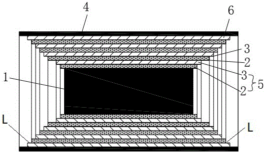
[0086] The structure and manufacturing process of the 10KV composite shielded insulated copper tube busbar are as follows:

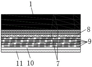
[0087] Step 1: Leave 20cm at both ends of the conductor, and then wrap 2 layers of PTFE oriented film tightly on the surface of the conductor.

[0088] Step 2: Tightly wrap a layer of aluminum foil on the outside of the PTFE oriented film.

[0089] Step 3: Wrap 4 layers of polytetrafluoroethylene around the aluminum foil, and apply silicone oil evenly

[0090] Step 4: Install a transparent heat-shrinkable sleeve containing polytetrafluoroethylene on the outer surface of the polytetrafluoroethylene oriented film. Steps 1, 2, 3, and 4 can be regarded as the first insulation shielding layer, and then leave 5cm at both ends of each insulation shielding layer to make the second, third, and fourth insulation shielding layers, a total of four For the insulating shielding layer, heat shrink two layers of insulating sheath outside the fourth insulating shieldin...

Embodiment 2

[0092] The structure and manufacturing process of the 35KV tubular composite shielding insulating tube busbar are as follows:

[0093] A. Step 1, leave 20cm at both ends of the conductor, and then tightly wrap two layers of PTFE oriented film on the surface of the conductor.

[0094] B. Step 2: Tightly wrap a layer of aluminum foil outside the PTFE oriented film.

[0095] C. Step 3: Wrap 4 layers of polytetrafluoroethylene around the aluminum foil and apply silicone oil evenly

[0096] D. Step 4: Set a transparent heat-shrinkable sleeve containing polytetrafluoroethylene on the outer surface of the polytetrafluoroethylene oriented film. E. Steps 1, 2, 3, and 4 can be regarded as the first insulating shielding layer, and then leave 5cm at both ends of each insulating shielding layer for the second, third, fourth, fifth, sixth, and second Seventh, the production of the eighth insulation shielding layer, a total of eight insulation shielding layers, heat shrink two layers of in...


PUM


Abstract

The invention discloses a tubular composite shielded and insulated bus comprising a tubular conductor, and a plurality of insulating and shielding layers and an outer sheath layer which coat the tubular conductor in sequence. Each insulating and shielding layer consists of an insulating layer and a shielding layer connected in sequence. At the joint of each insulating and shielding layer and the tubular conductor, two sections of the same length are respectively reserved outward at the two ends of the insulating and shielding layer. Thus, a stepped insulating and shielding part is formed inside the tubular conductor. The shielding layer closest to the outer sheath layer is a grounding shielding layer. The tubular composite shielded and insulated bus of the invention has the advantages of strong electrical insulation performance, high insulation safety coefficient, large carrying capacity, low skin effect, good heat dissipation conditions, small temperature rise, high mechanical strength, large allowable stress [sigma], high electric shock resistance, no environmental disturbance, high safety and reliability, novel appearance, simple structure, convenient installation, less maintenance workload and less space occupation, and is suitable for construction layout in all kinds of complicated sites.

Description

technical field [0001] The invention relates to the technical field of composite shielded insulating busbars, in particular to a tubular composite shielded insulating busbar and its manufacturing process, which can effectively improve the insulation strength of copper tube busbars, shield electromagnetic interference, reduce eddy current losses generated during product operation, and reduce A new type of insulation protection processing technology for conductive materials for partial discharge. Background technique [0002] Composite shielded insulated copper busbar is one of the important components in the power transmission and distribution system, and its external insulation protection plays a vital role in the safe and reliable operation of the power transmission and distribution system and power equipment. Composite shielded insulated copper tube busbar is mainly used for power transmission and distribution of various voltage levels in various power plants and substatio...

Claims


Application Information

Patent Timeline
IPC IPC(8): H01B7/00H01B7/02H01B7/282H01B7/30H01B7/42H01B9/02H01B13/00H01B13/06H01B13/22
CPCH01B9/021H01B7/0009H01B7/0225H01B7/282H01B7/30H01B7/421H01B9/008H01B13/00H01B13/06H01B13/22
Inventor 邵成才檀冰花李润
Owner JIANGSU PENGZHENG MECHANICAL & ELECTRICAL EQUIP
Learn More