
Eureka
For R&D, Eureka makes reading and utilizing patents & technical documents easy.
Eureka AIR
Designed for self-driven R&D workflows. Generate viable solutions, solve complex R&D challenges, empower your innovation with AI.

Eureka Materials
Designed for material experts only. Revolutionize your material R&D, from search, analyze, to developing new materials.

TechResearch
Generate reliable direction feasibility study reports for your R&D in just a few steps.

TechSeek
Discover and master advanced knowledge NOW. Basics, ideas, possibilities, all at once.

TechMind
As an expert in R&D Theories, TechMind can generates customized viable solutions instantly.

TechRisk
Analyze your overall solution with one click, know your potential R&D risks in advance.

TechMonitor
Get weekly tech updates, stay abreast of the latest tech innovations and key insights.
System and method for treating rapid coal pyrolysis effluent
A waste water and pyrolysis technology, applied in chemical instruments and methods, biological water/sewage treatment, heating water/sewage treatment, etc., can solve the problems of high treatment cost, high equipment requirements, and inability to be used on a large scale to achieve high efficiency Effects of energy saving, emission reduction and process structure optimization
- Summary
- Abstract
- Description
- Claims
- Application Information
AI Technical Summary
Problems solved by technology
Method used
Image

Examples
Embodiment 1
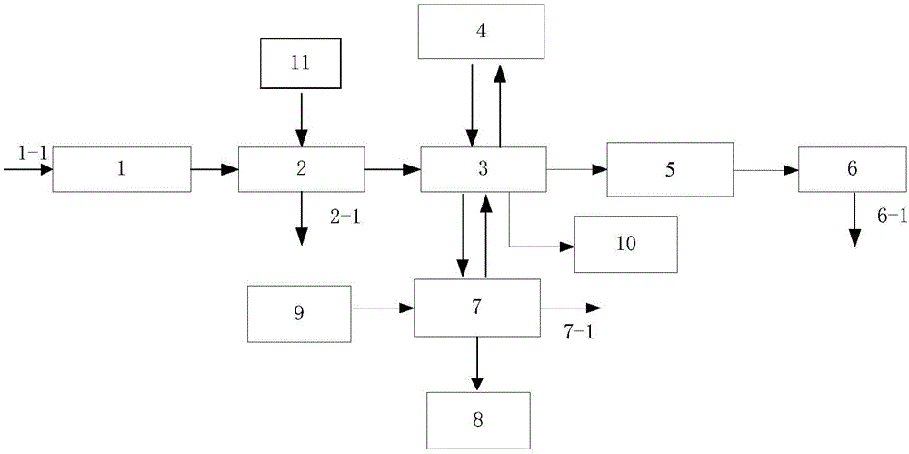
[0073] This embodiment provides a system for processing and processing coal rapid pyrolysis wastewater, and its structure diagram is as figure 1 Shown. Specifically include: wastewater homogenization tank 1, grease trap 2, waste heat recovery device 3, steam stripper 4, A 2 O Biochemical reaction tank 5, sedimentation tank 6, alkaline washing tank 7, phenol storage tank 8, lye dosing tank 9, ammonia storage tank 10 and dosing machine 11.
[0074] The wastewater homogenization tank 1 is equipped with a submersible mixer, which can better homogenize the wastewater. The wastewater homogeneous tank 1 is provided with a homogeneous wastewater inlet 1-1 and a homogeneous wastewater outlet.
[0075] The grease trap 2 is provided with a pyrolysis wastewater inlet, a demulsifier inlet, a degreasing wastewater outlet, and a sludge outlet 2-1. The pyrolysis wastewater inlet is connected to the homogeneous wastewater outlet of the wastewater homogenization tank 1. The top and bottom of the gr...
Embodiment 2
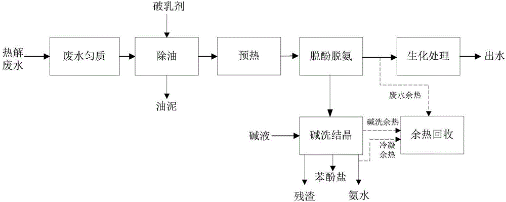
[0082] This embodiment provides a method for treating coal rapid pyrolysis wastewater by using the system provided in Embodiment 1. Specific process flow such as figure 2 Shown.
[0083] The water quality of the coal rapid pyrolysis wastewater used in this embodiment is as follows:
[0084] COD=15000mg / L, BOD=6090mg / L, ammonia nitrogen=1800mg / L, volatile phenol=11000mg / L, pH=10.
[0085] After the wastewater is discharged from the rapid pyrolysis system, it enters the wastewater homogenization tank 1 for centralized treatment. The residence time of the pyrolysis wastewater in the wastewater homogenization tank 1 is 8h.
[0086] The wastewater discharged from the wastewater homogenization tank enters the grease trap 2. The dosing machine 11 adds a demulsifier to the grease trap 2, and the oil scraper and the mud scraper remove the slick oil and sludge in the wastewater respectively.
[0087] The waste water discharged from the grease trap 2 enters the waste heat recovery device 3 to...
PUM
 Abstract
Description
Claims
Application Information
 - R&D Engineer
- R&D Manager
- IP Professional
- Industry Leading Data Capabilities
- Powerful AI technology
- Patent DNA Extraction
Browse by: Latest US Patents, China's latest patents, Technical Efficacy Thesaurus, Application Domain, Technology Topic, Popular Technical Reports.
© 2024 PatSnap. All rights reserved.Legal|Privacy policy|Modern Slavery Act Transparency Statement|Sitemap|About US| Contact US: help@patsnap.com