R-Fe-B type sintered magnet manufacturing method

A technology of sintered magnets and manufacturing methods, which is applied in the manufacture of permanent magnets, inductors/transformers/magnets, magnetic objects, etc., can solve the problems of oxidation and shedding of heavy rare earth layers, difficult control, and difficulty in swinging materials.

Active Publication Date: 2017-01-04
YANTAI ZHENGHAI MAGNETIC MATERIAL CO LTD
View PDF7 Cites 9 Cited by
  • Summary
  • Abstract
  • Description
  • Claims
  • Application Information

AI Technical Summary

Problems solved by technology

Its shortcomings are also obvious, mainly because the actual production process can easily lead to the destruction of the surface state of the magnet. During the diffusion process, a large concentration difference is formed in the direct contact part with the heavy rare earth element, and the heavy rare earth element enters the main phase, thus causing the magnet The residual magnetism is reduced, and the heavy rare earth layer on the surface of the magnet will oxidize and fall off during the actual production process, which cannot be completely diffused into the magnet, resulting in waste of heavy rare earth, and the magnet cannot be in direct contact with the magnet during heat treatment. The problem of sticking will occur in contact, so it is necessary to add a partition between the magnets, which takes up a lot of space and results in a significant reduction in the amount of charge
The vacuum evaporation method uses brackets and other components to isolate the magnet from the heavy rare earth elements, and the heavy rare earth elements form steam by heating, and the steam diffuses around the magnet and slowly diffuses into the inside of the magnet. Evaporated material forms a support frame to prevent the direct contact between the magnet and the heavy rare earth elements, which greatly increases the difficulty of swinging the material. At the same time, the material frame occupies a large space and the loading amount is greatly reduced, and the support frame is generally made of high-cost materials. , which greatly increases the cost of processing equipment, and because the evaporation method is difficult to control the steam concentration, the process monitoring and equipment requirements are relatively high, and the consistency of the magnet after diffusion is slightly worse than that of the contact method; so the above two methods There are obvious deficiencies in the mass production process

Method used


Image

  • R-Fe-B type sintered magnet manufacturing method
  • R-Fe-B type sintered magnet manufacturing method

Examples


Embodiment 1

[0019] A vacuum melting furnace is used to smelt the configured raw materials under the protection of inert gas to form scales with a thickness of 0.1-0.5 mm. The metallographic grain boundaries of the R-Fe-B alloy scales are clear. The alloy scales are crushed mechanically, and jet milled after hydrogen explosion to crush the SMD to 3.4μm. The magnetic field orientation press molding of 15KOe is used to make a compact, and the density of the compact is 3.95g / cm3. The compact is vacuum sintered in a sintering furnace, firstly at 1080°C for 330min. Then perform aging treatment, aging at 480° C. for 240 minutes to obtain a green body. The green body is multi-wire cut into a magnetic sheet of the final product size. The size of the magnetic sheet: 27mm*15mm*5mm, tolerance: ±0.05mm.

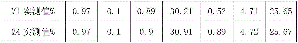
[0020] The surface of the magnetic sheet was washed with acid solution and deionized water, and dried to obtain the treated magnet M1. The composition of M1 is shown in Table 2. First, a layer of ...

Embodiment 2

[0027] A vacuum melting furnace is used to smelt the configured raw materials under the protection of inert gas to form scales with a thickness of 0.1-0.5 mm. The metallographic grain boundaries of the R-Fe-B alloy scales are clear. The alloy scales are crushed mechanically, and jet milled after hydrogen explosion to crush the SMD to 3.4μm. The magnetic field orientation press molding of 15KOe is used to make a compact, and the density of the compact is 3.95g / cm3. The compact is vacuum sintered in a sintering furnace, firstly at 1080°C for 330min. Then perform aging treatment, aging at 480° C. for 240 minutes to obtain a green body. The green body is multi-wire cut into a magnetic sheet of the final product size. The size of the magnetic sheet: 27mm*15mm*5mm, tolerance: ±0.05mm.

[0028] The surface of the magnetic sheet was washed with acid solution and deionized water, and dried to obtain the treated magnet M1. The composition of M1 is shown in Table 3. First, a layer of ...

Embodiment 3

[0035] A vacuum melting furnace is used to smelt the configured raw materials under the protection of inert gas to form scales with a thickness of 0.1-0.5 mm. The metallographic grain boundaries of the R-Fe-B alloy scales are clear. The alloy scales are crushed mechanically, and jet milled after hydrogen explosion to crush the SMD to 3.4μm. The magnetic field orientation press molding of 15KOe is used to make a compact, and the density of the compact is 3.95g / cm3. The compact is vacuum sintered in a sintering furnace, firstly at 1080°C for 330min. Then perform aging treatment, aging at 480° C. for 240 minutes to obtain a green body. The green body is multi-wire cut into a magnetic sheet of the final product size. The size of the magnetic sheet: 27mm*15mm*5mm, tolerance: ±0.05mm.

[0036] The surface of the magnetic sheet was washed with acid solution and deionized water, and dried to obtain the treated magnet M1. The composition of M1 is shown in Table 2. First, a layer of ...


PUM

PropertyMeasurementUnit
particle diameteraaaaaaaaaa
thicknessaaaaaaaaaa
thicknessaaaaaaaaaa

Abstract

The invention discloses an R-Fe-B type sintered magnet manufacturing method. The method mainly includes the steps that an R-Fe-B type sintered magnet is prepared as a matrix; a heavy rare earth RHX layer comprising at least one of metal dysprosium, dysprosium hydride, terbium and terbium hydride is distributed on the surface of the matrix, and an RLF layer comprising at least one of praseodymium fluoride, neodymium fluoride, praseodymium oxide and neodymium oxide is distributed on the RHX layer; heat treatment is conducted in a diffusion furnace, the heavy rare earth RHX is diffused into the magnet through the surface of the matrix. By arranging the RLF layer with praseodymium fluoride, neodymium fluoride, praseodymium oxide and neodymium oxide coatings outside the heavy rare earth RHX layer of the magnet, on one hand, magnets can be stacked in the diffusion process and the adhesion is prevented; on the other hand, the heavy rare earth RHX layer is protected against oxidation in the diffusion process, the situation that the heavy rare earth RHX layer is oxidized on the surface of the magnet and influences the diffusion effect is affected, besides, volatilization of the R element in the R-Fe-B type magnet matrix can be prevented in the diffusion process, and it is guaranteed that remanence of the magnet hardly reduces.

Description

technical field [0001] The invention relates to a method for manufacturing an R-Fe-B type sintered magnet, belonging to the field of rare earth permanent magnet materials. Background technique [0002] With the rapid development of new energy vehicles, the demand for permanent magnet motors in the field of new energy vehicles is increasing, and because the operating temperature of the motor in new energy vehicles is higher, magnets with higher coercivity are required, but due to the increase The coercive force requires a large amount of heavy rare earth elements, resulting in a sharp increase in the cost of the magnet, and adding a large amount of heavy rare earth directly in the smelting process will also cause a decrease in the magnetic energy product of the magnet. Since new energy vehicles require high coercive force and also need Therefore, how to reduce the use of heavy rare earth elements to produce magnets with high coercive force and high energy product has become a...

Claims


Application Information

Patent Timeline
Patent Type & Authority Applications(China)
IPC IPC(8): H01F1/057H01F41/02B22F3/10
CPCB22F3/1007B22F2999/00H01F1/0577H01F41/026B22F2201/20B22F3/10H01F1/0557H01F1/057H01F41/02
Inventor 李志强毛琮尧邵梅竹尼洪香
Owner YANTAI ZHENGHAI MAGNETIC MATERIAL CO LTD
Why Eureka
Try Eureka