

Sintering flue gas reduction and waste heat comprehensive utilization method and device
A technology for sintering flue gas and waste heat, applied in the new process field, can solve the problems of unavailability, excessive chimney emissions, integrated device load-bearing, material and wear requirements, and achieves the effect of saving energy consumption and reducing flue gas emissions.
- Summary
- Abstract
- Description
- Claims
- Application Information
AI Technical Summary
Problems solved by technology
Method used
Image

Examples
Embodiment
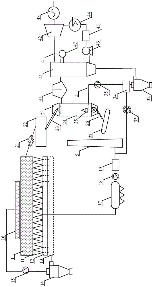
[0096] The sintering machine area of a steel company is 132m 2 , There are 18 bellows branch pipes under the sintering machine trolley. The sintering machine is equipped with a main exhaust fan. The flue gas parameters of the main exhaust flue flue are relatively large, and the flue gas volume is 45-55Nm 3 / h, the average smoke temperature is 220-260°C, the moisture content is 9.5-12.6% (volume ratio), the oxygen content is 13.4-17.3% (volume ratio), and the content and concentration of each pollutant vary widely.
[0097] The original technological process of sintering production waste gas treatment and waste heat utilization is: sintering waste gas is led to the main exhaust flue through the branch pipes of the bellows, mixed, sent to the electrostatic precipitator by the main exhaust fan, and then discharged from the chimney after being treated by the flue gas desulfurization facility. At the same time, the red-hot sintered ore falls into the ore bin through the tail end ...
PUM
 Abstract
Description
Claims
Application Information