
Gas field sulfur-containing waste gas treatment method

A technology for waste gas treatment and gas fields, which is applied in gas treatment, separation methods, chemical instruments and methods, etc., can solve the problems of difficult to treat waste water, difficult to meet the standard, and difficult to adapt to the exhaust gas, so as to improve the desulfurization efficiency and desulfurization performance, and accelerate the regeneration efficiency. , the effect of simplifying the process and operation

Inactive Publication Date: 2017-05-17
四川沃兹凯兰科技有限公司
View PDF4 Cites 8 Cited by
  • Summary
  • Abstract
  • Description
  • Claims
  • Application Information

AI Technical Summary

Problems solved by technology

However, the degradation of the catalyst during operation, the generation of a large amount of secondary salts and the difficult treatment of highly toxic sewage have always been the bottleneck of the technical application of this method.
[0008] Obviously, the Claus combustion method is uneconomical or even inoperable for low-concentration, low-volume acid gases
However, the aqueous phase wet oxidation method is difficult to adapt to the market demand for high-concentration and low-volume acid gas treatment, especially the secondary pollution problems such as tail gas difficult to meet standards and difficult-to-treat wastewater in the current sulfur resource utilization technology.

Method used


Image

  • Gas field sulfur-containing waste gas treatment method

Examples


specific Embodiment 1

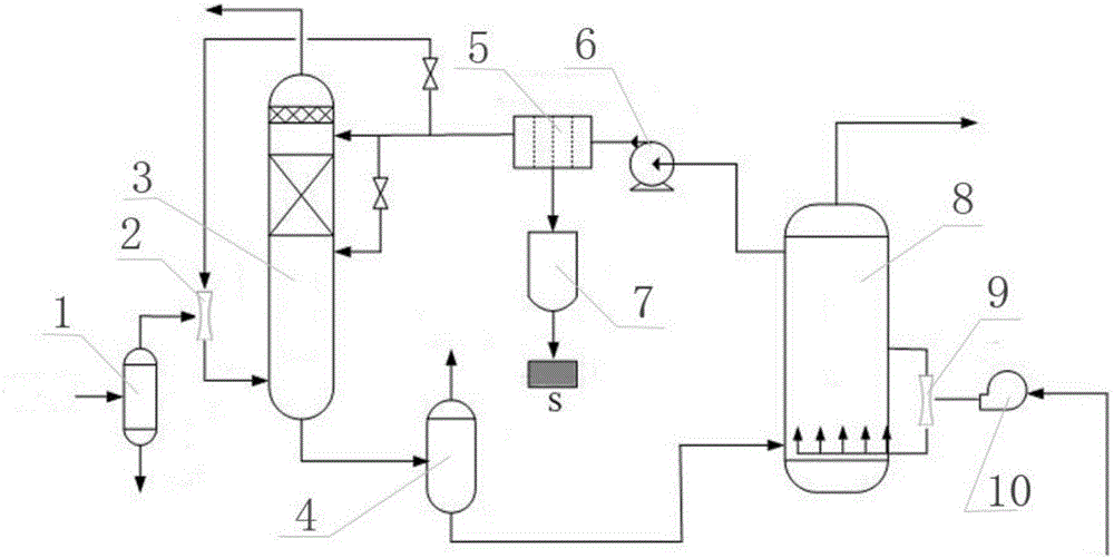
[0039] A method for treating sulfur-containing waste gas from a gas field, comprising the steps of:

[0040] (1) The raw material gas is separated into free water through the gas-liquid separator 1;

[0041] (2) The raw material gas separated from free water enters the absorption tower 3 through the Venturi tube-2 jet flow, and the temperature in the absorption tower is 20~180° C., and the pressure is normal pressure;

[0042] (3) The desulfurization solution enters the absorption tower 3 and mixes with the raw material gas of step (two), the divalent sulfur in the raw material gas in the absorption tower 3 is directly converted into sulfur, and the purified gas is discharged from the top of the absorption tower 3, and the desulfurization is poor The liquid enters the upper middle part and the bottom of the absorption tower 3 in two ways, the absorption tower 3 uses a bubble tower or a packed tower, the purified gas can be recycled, and the H2S in the purified gas is <10mg / m3;...


PUM


Abstract

The invention relates to a waste gas treatment process, in particular to a gas field sulfur-containing waste gas treatment method. The method comprises the following steps that raw material gas is treated by a gas-liquid separator to separate out free water; the raw material gas subjected to the free water separation enters an absorption tower in a jet flow manner through a first Venturi tube; a desulfurization solution enters the absorption tower to be mixed with the raw material gas in the second step; bivalent sulfur in the raw material gas in the absorption tower is directly converted into sulfur; purified gas is exhausted from the top of the absorption tower through a defoaming device; after generated sulfur particles pass through a filtering machine or a filter press, sulfur filter cake is obtained; the filter cake enters a sulfur melting kettle to obtain a sulfur product; the desulfurization solution flows into a flash tank after taking reaction in the absorption tower; after flashing, desulfurization rich liquid enters a regeneration tower; the desulfurization rich liquid in the regeneration tower is subjected to oxidation and regeneration, air is subjected to fan pressurization and Venturi tube jet flow to be mixed with the desulfurization rich liquid; the mixed desulfurization solution enters the regeneration tower in a bubbling or aeration mode; after the regeneration, desulfurization barren liquid enters a plate frame filter or the filter press through a solution circulation pump; after being filtered, the desulfurization solution enters the absorption tower to be cyclically used.

Description

technical field [0001] The invention relates to a waste gas treatment process, in particular to a treatment method for sulfur-containing waste gas from a gas field. Background technique [0002] Sulfur-containing waste gas from gas fields has some common characteristics: the gas flow rate is usually not large, ranging from several hundred cubic meters per day to tens of thousands of cubic meters per day; the types of sulfur-containing substances are mainly H 2 Mainly S, may be accompanied by a small amount of organic sulfur, if it is burned, it will become SO 2 ; H in exhaust gas 2 The concentration of S varies greatly, ranging from a few hundred milligrams per cubic meter when it is low to several percent or even tens of percent when it is high. According to the above characteristics, the selection of desulfurization method mainly considers the use of redox absorption method, solid adsorption method and lye absorption method. [0003] For small and medium-scale desulfuri...

Claims


Application Information

Patent Timeline
IPC IPC(8): B01D53/78B01D53/52C01B17/05
CPCB01D53/78B01D53/52B01D2251/00B01D2251/60B01D2258/02C01B17/05
Inventor 罗小平韩志刚贾玉刚杨明军
Owner 四川沃兹凯兰科技有限公司
Learn More