
Coal shaft furnace direct reduction process

A coal-based, shaft furnace technology, applied in shaft furnaces, improvement of process efficiency, furnaces, etc., can solve problems such as production constraints, unreasonable furnace top material distribution system, complex process, etc., to achieve large transportation and material distribution capabilities, and optimize the furnace The effect of topping fabric technology and simplifying the process flow

Inactive Publication Date: 2017-05-31
WUHAN COSRED SCI & TECH LTD
View PDF7 Cites 21 Cited by
  • Summary
  • Abstract
  • Description
  • Claims
  • Application Information

AI Technical Summary

Problems solved by technology

[0004] (1) The hearth of the rotary hearth furnace has been in circular motion, and the hearth is constantly in the cycle of heating and cooling, which brings about the easy damage of the bed refractory material, shortening its life, easy deformation of the bed structure, and reducing atmosphere. Difficult to control, low metallization rate of products, high energy consumption, production is limited by technology, and it is difficult to achieve large-scale production with an annual output of more than 400,000 tons;
[0005] (2) The rotary kiln has disadvantages such as high requirements for raw materials and fuels, easy ring formation in the kiln, difficult control of the temperature in the reduction zone, difficult operation, high energy consumption, unstable product quality, and the inability to achieve large-scale production with an annual output of more than 200,000 tons;
[0006] (3) Mechanized inclined tank loading in tunnel kiln is unstable, manual loading and unloading of tanks is labor-intensive, environmental protection is poor, and the reaction tank is in the process of repeated heating and cooling, resulting in low tank life, high energy consumption, and failure to achieve an annual output of more than 200,000 tons Disadvantages of mass production
[0008] (1) This process mixes iron ore powder containing iron oxides with a binder to form pellets. The outer layer of iron balls is covered with a layer of carbon powder and then oxidized by high-temperature flue gas to form double-layer oxidized pellets. Not only is the necessity poor, but also Complex process
[0009] (2) After the process is reduced, the separation of sponge iron and other powder materials adopts a vacuum negative pressure suction system, which has high energy consumption and is difficult to meet the needs of large-scale production
[0010] (3) The refractory material in the reduction chamber of this process is made of SiC material, which has poor oxidation resistance, low thermal conductivity, and limited life, resulting in high energy consumption and high cost
[0011] (4) Furnace top material distribution system is unreasonable, the output is severely restricted, and large-scale production of more than 200,000 tons cannot be realized
[0012] (5) This process only considers the hot discharge scheme, there is no cold treatment scheme, and the adaptability of the product is poor

Method used


Image

  • Coal shaft furnace direct reduction process
  • Coal shaft furnace direct reduction process

Examples


Embodiment 1

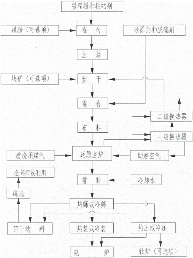
[0047] Such as figure 1 As shown, the invention provides a kind of coal-based shaft furnace direct reduction process for producing sponge iron, and its main production steps include:

[0048] 1) The iron concentrate powder and binder are fully mixed and then briquetted. The particle size of the briquette is 15-45mm, then dried, and mixed with reducing agent and desulfurizer after drying; iron concentrate powder and binder During the mixing process, a small amount of coal powder can be added as needed to improve the reduction efficiency; if the raw material is lump ore, there is no need for mixing and briquetting, and the drying and subsequent processes are directly carried out;

[0049] 2) The mixture is fed from the top of the reduction chamber by the material distribution device of the coal-based shaft furnace. The reduction chamber is completely filled with the mixture. The materials are dispersed and evenly distributed. The material surface is higher than the reduction fu...

Embodiment 2

[0065] The coal-based shaft furnace direct reduction process for producing sponge iron of the present invention comprises the following steps:

[0066] 1) Fully mix the iron fine powder with iron content of 64% and binder, and then briquette. The particle size after briquetting is about 25mm. After being dried by a dryer, it is transported to the silo under the tank;

[0067] 2) Mix the dried block material obtained above with anthracite reducing agent and limestone desulfurizer. It is required to mix as evenly as possible. The ratio of block material to reducing agent is about 1:0.4. The mixture is loaded from the top of the reduction furnace by the furnace top distributor. into the reduction chamber, the mixture will completely fill the reduction chamber and be higher than the top surface of the reduction furnace by a certain height;

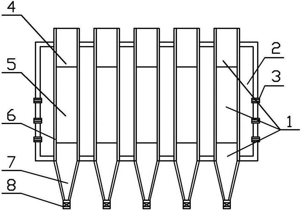
[0068] 3) The preheating section and reducing section of the reduction chamber are rectangular, with a width of 300-800mm, a length of 1000-1...


PUM

PropertyMeasurementUnit
Granularityaaaaaaaaaa

Abstract

The invention relates to a coal shaft furnace direct reduction process for production of sponge iron. The coal base shaft furnace direct reduction process for production of sponge iron comprises the following steps: uniformly mixing powdered iron with a binder, briquetting and drying; mixing the mixture with a reducing agent and a desulfurizing agent; feeding the mixed material into the reduction chamber of a coal shaft furnace through a material distribution device arranged at the top of the furnace; discharging the mixed material out of the furnace through a discharging device after the mixed material passes through the preheating section, the reduction section and the cooling section in the reduction chamber of the coal shaft furnace; performing hot sieving and cold sieving; directly feeding the mixed material into a melting device or feeding the mixed material into the melting device after briquetting; completely recycling the screen underflow after magnetic separation. The coal shaft furnace direct reduction process has the following obvious advantages: the technological process is simple and reliable, large-scale production is realized, the crude fuel adaptability is high, the energy is fully utilized, the cost is low, the product quality is good, wide product application is achieved, and the investment is low.

Description

technical field [0001] The invention relates to the technical field of metal pyrometallurgy, in particular to a coal-based shaft furnace direct reduction process, which is mainly used for producing sponge iron with high metallization rate. Background technique [0002] At present, the direct reduction technology for sponge iron production at home and abroad, according to the type of reducing agent, has two types: gas-based and coal-based. Gas-based mainly includes MIDREX (Midrex method), HYL (Hill method), etc.; coal-based There are mainly rotary kiln method, rotary hearth furnace method, tunnel kiln and so on. The above technologies all have their own shortcomings. The gas-based reduction technology requires high-quality reducing gas, the preparation and reforming process and equipment of the reducing gas are very complicated, the reduction process is difficult to control, the raw material requirements are high, the investment is large, and the operating cost is high. Some...

Claims


Application Information

Patent Timeline
IPC IPC(8): C21B13/02
CPCC21B13/02Y02P10/20
Inventor 李建涛
Owner WUHAN COSRED SCI & TECH LTD
Learn More