Ultrasonic transducer with optimized matching layers and manufacturing method thereof

A technology for ultrasonic transducers and manufacturing methods, applied in chemical instruments and methods, lamination auxiliary operations, lamination, etc., can solve the problems of large acoustic impedance mutation, large acoustic impedance gap, and influence of propagation efficiency, and achieve improved performance , Improve the effect of center frequency and frequency response bandwidth improvement

Inactive Publication Date: 2017-06-13
上海爱声生物医疗科技有限公司
View PDF8 Cites 0 Cited by
  • Summary
  • Abstract
  • Description
  • Claims
  • Application Information

AI Technical Summary

Problems solved by technology

If sound waves are directly injected from these piezoelectric materials into blood with low acoustic impedance, the transmission efficiency will be affected due to the large difference in acoustic impedance
[0008] For example, the acoustic impedance of the composite material is around 20MRayl, and it will be in direct contact with water or saline (1.5MRayl). The sudden change in acoustic impedance will affect the efficiency of acoustic energy from the transducer to the water.

Method used


Image

  • Ultrasonic transducer with optimized matching layers and manufacturing method thereof
  • Ultrasonic transducer with optimized matching layers and manufacturing method thereof
  • Ultrasonic transducer with optimized matching layers and manufacturing method thereof

Examples


Embodiment 1

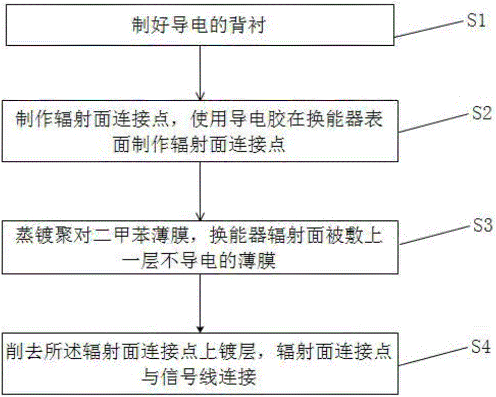
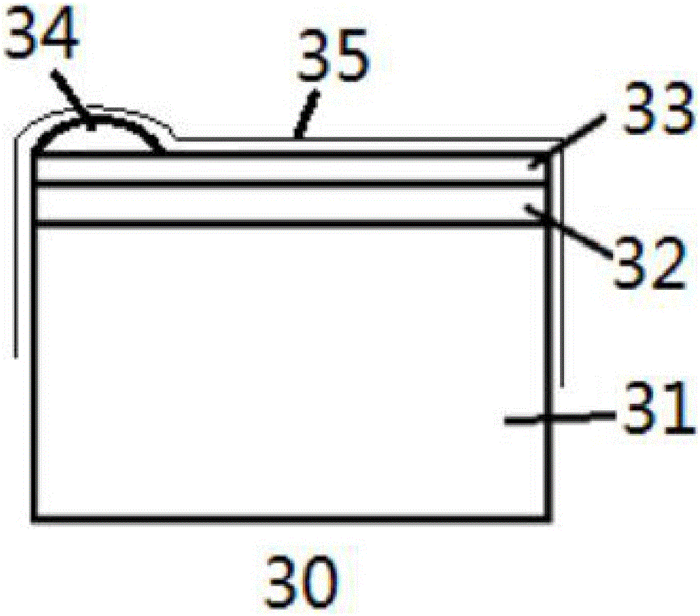
[0045] A kind of ultrasonic transducer with matching layer optimization, comprising: backing layer 31, piezoelectric crystal layer 32 and matching layer 33 connected successively, such as image 3 As shown, make the connecting point of the radiating surface. The conductive backing 31 and the conductive first matching layer 33 are prefabricated. If the piezoelectric crystal 32 is a composite material, the matching layer 33 does not need to be fabricated. The connection points 34 are made on the surface of the transducer using conductive glue.

[0046]Evaporate Parylene, after the first step is completed, perform Parylene evaporation, after the evaporation is completed. The radiating surface of the transducer will be coated with a non-conductive thin film 35, and this layer of thin film 35 is used as the second layer matching of the transducer. If the piezoelectric crystal 32 is a piezoelectric composite material, there is no first matching layer 33, Film 35 is the only layer ...

Embodiment 2

[0049] A kind of ultrasonic transducer with matching layer optimization, comprising: backing layer 31, piezoelectric crystal layer 32 and matching layer 33 connected successively, such as Figure 4 , Figure 5 As shown in the transducer 30, the conductive backing 31 and the conductive first matching layer 33 are prefabricated. If the piezoelectric crystal 32 is a composite material, the matching layer 33 does not need to be fabricated. The radiating surface of the transducer will be coated with a non-conductive thin film 35, and this layer of thin film 35 is used as the second layer matching of the transducer. If the piezoelectric crystal 32 is a piezoelectric composite material, there is no first matching layer 33, Film 35 is the only layer matched. The membrane 35 needs to be designed with an appropriate thickness to allow the transducer 30 to achieve optimal performance.

[0050] connecting cables such as Figure 6 The connecting wires on the Parylene coating 35 are cut ...

Embodiment 3

[0052] A kind of ultrasonic transducer with matching layer optimization, comprising: backing layer 31, piezoelectric crystal layer 32 and matching layer 33 connected successively, such as Figure 6 shown. For the transducer 30, the conductive backing 31 and the conductive first matching layer 33 are prefabricated. If the piezoelectric crystal 32 is a composite material, the matching layer 33 does not need to be fabricated. The radiating surface of the transducer will be coated with a non-conductive thin film 35, and this layer of thin film 35 is used as the second layer matching of the transducer. If the piezoelectric crystal 32 is a piezoelectric composite material, there is no first matching layer 33, Film 35 is the only layer matched. The membrane 35 needs to be designed with an appropriate thickness to allow the transducer 30 to achieve optimal performance.

[0053] Connect the cable, lift a small part of the parylene on the corner of the Parylene coating 35, where the r...


PUM

PropertyMeasurementUnit
frequencyaaaaaaaaaa

Abstract

The invention discloses an ultrasonic transducer with optimized matching layers and a manufacturing method thereof. The ultrasonic transducer comprises a back lining layer, a piezo-electric crystal layer and one or the multiple matching layers, wherein the back lining layer, the piezo-electric crystal layer and the matching layers are sequentially connected. The piezo-electric crystal layer is made of a composite single crystal pressure material, and the surface of the composite single crystal pressure material is coated with the poly-p-xylylene thin film matching layers. The manufacturing method comprises the following steps that a conductive back lining is manufactured, a radiating surface connecting point is manufactured, a conductive adhesive is used for manufacturing the radiating surface connecting point on the surface of a transducer body, a poly-p-xylylene thin film is subjected to evaporation, the radiating surface of the transducer body coated with a non-conductive thin film, and the radiating surface connecting point and a signal wire are connected. According to the ultrasonic transducer with the optimized matching layers and the manufacturing method thereof, the properties of the ultrasonic imaging ultrasonic transducer in a blood vessel are improved, the ultrasonic imaging image resolution in blood vessel is improved, and the penetration depth of images is improved.

Description

technical field [0001] The invention relates to the field of ultrasonic transducers, in particular to an ultrasonic transducer with an optimized matching layer and a manufacturing method thereof. Background technique [0002] Intravascular Ultrasound (IVUS) imaging is a catheter ultrasound imaging technique used to diagnose coronary atherosclerosis and guide percutaneous coronary stenting. Intravascular ultrasound is a new diagnostic method combining non-invasive ultrasound technology and minimally invasive catheter technology. Intravascular ultrasound is the use of catheter technology to introduce a high-frequency micro-ultrasound transducer into the coronary artery cavity for detection, and obtain cross-sectional imaging of each layer of the vessel wall to assist clinicians in diagnosing intravascular lesions. [0003] The intravascular ultrasound imaging system includes three main components: an intravascular ultrasound catheter equipped with an ultrasound probe, a retra...

Claims


Application Information

Patent Timeline
Patent Type & Authority Applications(China)
IPC IPC(8): B06B1/06B32B9/00B32B9/04B32B33/00B32B38/00
CPCB06B1/06B32B9/00B32B9/04B32B33/00B32B38/00B32B2255/26B32B2307/206
Inventor 李翔陈友伟袁建人林钟霞
Owner 上海爱声生物医疗科技有限公司
Why Eureka
Try Eureka