
Quantum dot spectral imaging system

A spectral imaging and quantum dot technology, applied in the field of spectral imaging, can solve the problems of limited number of spectral bands, limited number of bands, loss of light energy, etc., and achieve the effects of reducing complexity, reducing development costs, and high energy utilization

Inactive Publication Date: 2017-06-20
ACAD OF OPTO ELECTRONICS CHINESE ACAD OF SCI
View PDF3 Cites 11 Cited by
  • Summary
  • Abstract
  • Description
  • Claims
  • Application Information

AI Technical Summary

Problems solved by technology

[0004] 1) There are slits in the dispersive imaging spectrometer or Fourier transform imaging spectrometer, which will greatly cause the loss of light energy and limit the improvement of the signal-to-noise ratio of the spectral camera
This type of instrument requires complex spectroscopic devices, such as spectroscopic prisms or diffraction gratings, resulting in bulky, expensive, and difficult to develop systems, and it is difficult to meet the requirements of miniaturized loads.
For example, the hyperspectral imager of Germany's EnMap uses a spectrometer with a Fery curved prism. The system of the Fery curved prism spectrometer is large, and a slit is placed on the rear focal plane of the front telescope, resulting in a great loss of energy.
Complex optical systems are required, and these structures usually include a large number of light-splitting elements and require very high installation accuracy, which will increase the weight, volume and development cost of the system, and it is difficult to meet the requirements of miniaturization of the load
[0005] 2) Imaging spectrometers using optical filters or linear gradient filters can meet the needs of miniaturization, but the number of bands is limited, and there are deficiencies in photon efficiency, spectral resolution and narrow spectral range
For example, the multi-spectral camera with filter array developed by Xi'an Optical Machinery has added a filter to the camera system, placed it in front of the CCD detector, and plated it on the filter substrate along the direction perpendicular to the flight. Multiple narrowband filters; however, the filter coating process limits the number of spectral bands and cannot be used as a hyperspectral imager

Method used


Image

  • Quantum dot spectral imaging system
  • Quantum dot spectral imaging system
  • Quantum dot spectral imaging system

Examples


Embodiment Construction

[0039] The technical solutions in the embodiments of the present invention will be clearly and completely described below in conjunction with the accompanying drawings in the embodiments of the present invention. Obviously, the described embodiments are only some of the embodiments of the present invention, not all of them. Based on the embodiments of the present invention, all other embodiments obtained by persons of ordinary skill in the art without making creative efforts belong to the protection scope of the present invention.

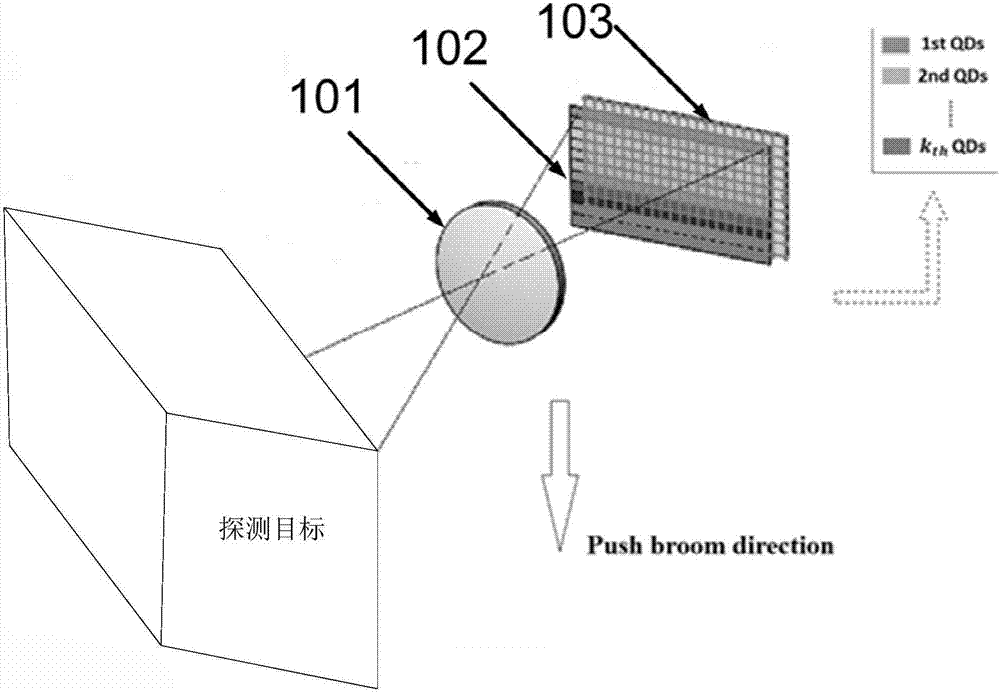
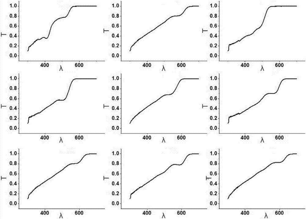
[0040] figure 1 A kind of quantum dot spectral imaging system provided for the embodiment of the present invention, such as figure 1 As shown, it mainly includes: a front telescope 101, a quantum dot array sheet 102 and an image detector 103 arranged in sequence; the image detector 103 is located at the rear focal plane of the front telescope 101; as figure 2As shown, the quantum dot array sheet 101 is made of quantum dot materials with different...


PUM


Abstract

The invention discloses a quantum dot spectral imaging system which comprises a front telescope, a quantum dot array plate, and an image detector arranged in order. The image detector is at the back focal plane of the front telescope. According to the quantum dot array plate, quantum dot materials with different spectral transmission rate characteristics are parallelly made on a substrate along a spectral dimension direction, each quantum dot material covers one or more rows of detection pixels in the spectral dimension direction, and a quantum dot strip is formed. The scheme is based on the quantum dot spectral imaging system, compared with a traditional spectral imager, the system has the advantages of stable performance, a high energy utilization rate, a simple structure, a small volume, a light weight and low cost, the complexity and development cost of the system are effectively reduced, the system is suitable for airborne or spaceborne equipment, and especially the application requirement of load miniaturization is satisfied. In addition, an incident spectrum can be restored well by using a spectral reconstruction algorithm.

Description

technical field [0001] The invention relates to the technical field of spectral imaging, in particular to a quantum dot spectral imaging system. Background technique [0002] Spectral imaging technology is a new type of multi-dimensional information acquisition technology that combines imaging technology and spectral technology. It can obtain two-dimensional spatial information and one-dimensional spectral information of the detected target to form a data cube. Spectral imaging technology can realize comprehensive detection, perception and recognition of target characteristics, greatly expands the monitoring capability and target recognition of remote sensing detection technology, and has irreplaceable advantages of other remote sensing technologies. According to the different working principles of spectral imagers, spectral imagers can be divided into dispersion type, interference type, filter type and computational spectral imaging type. [0003] At present, the miniaturi...

Claims


Application Information

Patent Timeline
IPC IPC(8): G01J3/28
CPCG01J3/2823
Inventor 魏立冬王英俊周锦松景娟娟李雅灿杨雷付锡禄王欣
Owner ACAD OF OPTO ELECTRONICS CHINESE ACAD OF SCI
Learn More