
Harmless and recycling treatment method and process for oily sludge

A treatment method and sludge technology, which is applied in the field of harmless and resource-based treatment, achieves the effects of large treatment volume, reduced treatment cost and solution to pollution problems

Inactive Publication Date: 2017-06-30
XIAN HUANUO ENVIRONMENTAL PROTECTION CO LTD
View PDF4 Cites 15 Cited by
  • Summary
  • Abstract
  • Description
  • Claims
  • Application Information

AI Technical Summary

Problems solved by technology

The technical scheme of the present invention can solve the resource treatment of oily sludge in the oil field production process, and can also solve the problem of comprehensive treatment and utilization of sludge, so that oil, water and mud in oily sludge can be separated, and there will be no secondary Secondary pollution, can achieve comprehensive utilization, large treatment capacity, large-scale production, can reduce treatment costs, completely solve the pollution problem of oily sludge, achieve harmless, resourceful, and reduction of oily sludge, and can protect Environment, conducive to the sustainable development of oil fields

Method used


Image

  • Harmless and recycling treatment method and process for oily sludge

Examples


Embodiment 1

Embodiment 2

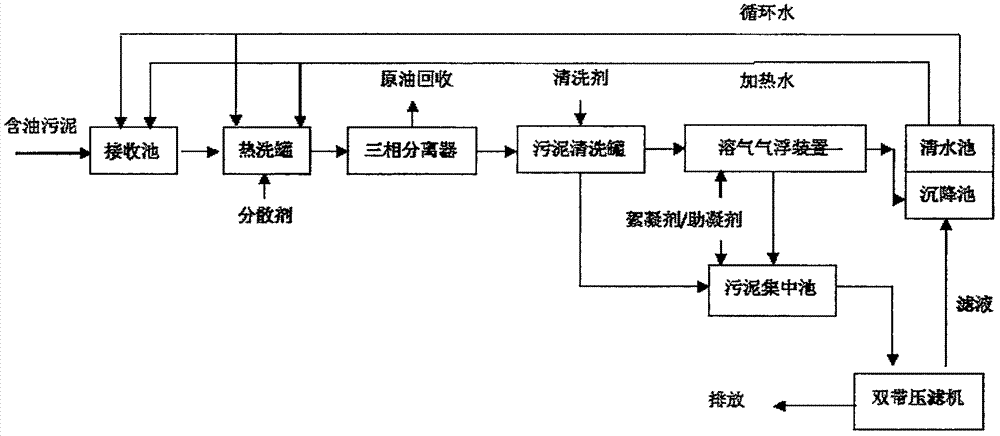
[0035] Example 2: The untreated sludge at the on-site sludge treatment station of an oil production plant in the Yanchang Oilfield contains 21.99wt% oil, 42.93wt% water, and 35.08wt% impurities. The specific treatment method is the same as in Example 1, that is: The sludge is diluted 2 times by circulating water in the receiving tank, and enters the hot washing tank after reaching a fluid state. The oily sludge is further diluted to 5 times the original sludge in the hot washing tank, and the oily sludge mixture is heated to 60°C. The dispersant enters the sludge cleaning tank, and then the crude oil is separated from the sludge by adding the cleaning agent; after the sludge is collected in the sludge concentration tank, it is processed by a double-belt filter press, and a bio-accelerator is added outside. Transported to the drying yard, the treated oily sludge contains 0.30wt% oil, 37.87wt% water, and 61.83wt% impurities. The heavy metal ions meet the discharge standard, and t...

Embodiment 3

[0036] Example 3: The sludge containing 25.18wt% oil, 32.27wt% water, and 42.55wt% impurity after tempering treatment at the on-site sludge treatment station of an oil production plant in the Yanchang Oilfield. The specific treatment method is the same as in Example 1, that is, by The oily sludge is diluted 2 times by circulating water in the receiving tank, and enters the hot washing tank after it reaches a fluid state. The oily sludge is further diluted to 5 times of the original sludge in the hot washing tank, and the oily sludge mixture is heated to 80°C and put into the tank. Add dispersant, enter the sludge cleaning tank, and then separate the crude oil from the sludge by adding cleaning agent; after the sludge is collected in the sludge concentration tank, it is processed by a filter press, added with an accelerator, and transported to In the drying yard, after treatment, the oily sludge contains 0.275wt% of oil, 38.89wt% of water, and 60.835wt% of impurities. The heavy ...


PUM


Abstract

The invention relates to a hot washing separation treatment method for the oily sludge. The hot washing separation treatment method comprises steps as follows: (1) the oily sludge is introduced into a receiving tank and diluted with circulating water, and enters a hot washing tank through a lift pump after being in a fluid state; (2) a dispersant is added to the hot washing tank, so that crude oil is separated from the sludge and enters a three-phase separator; and the like. The treatment method has the advantages that oil, water and sludge in the oily sludge are separated, secondary pollution cannot be caused, comprehensive utilization can be realized, the treatment amount is large, large-scale production can be realized, the treatment cost can be reduced, the pollution problem of the oily sludge is thoroughly solved, harmlessness, recycling and reduction of the oily sludge are realized, the environment can be protected, and sustainable development of an oil field is facilitated.

Description

technical field [0001] The invention relates to the technical field of petroleum industry environmental protection, in particular to a harmless and resourceful treatment method and process for oily sludge. . Background technique [0002] Oily sludge mainly comes from oily solid waste produced in the process of oil exploration, oil development, oil transportation, oil refining, and oily sewage treatment. The process includes the sediment deposited in large crude oil tanks, the oily sludge produced by sewage treatment, and the oily sludge that has landed due to sudden environmental pollution incidents and other reasons. Such as the generated crude oil sludge, pool bottom sludge, etc. [0003] Oily sludge is a high-viscosity chemically stable suspension emulsion system, which contains a large amount of aged oil, wax, asphaltene, colloid and solid suspended matter, bacteria, salts, acid gas, corrosion products, etc. Its nature is that heavy oil sludge has poor fluidity, high ...

Claims


Application Information

Patent Timeline
Patent Type & Authority Applications(China)
IPC IPC(8): C02F11/00C02F103/36
CPCC02F1/24C02F1/5263C02F1/56C02F11/00C02F11/002C02F11/02C02F11/12C02F11/122C02F11/123C02F11/14C02F11/18C02F2101/32C02F2103/10C02F2103/365C02F2301/046C02F2301/08
Inventor 张峰
Owner XIAN HUANUO ENVIRONMENTAL PROTECTION CO LTD
Learn More