Three-phase catalytic deodorization process for RTO emission exhaust
A three-phase, tail gas technology, applied in physical/chemical process catalysts, metal/metal oxide/metal hydroxide catalysts, organic compound/hydride/coordination complex catalysts, etc., can solve problems such as odor pollution, To achieve the effect of efficient degradation, low cost and simple operation
- Summary
- Abstract
- Description
- Claims
- Application Information
AI Technical Summary
Problems solved by technology
Method used
Image

Examples
Embodiment 1
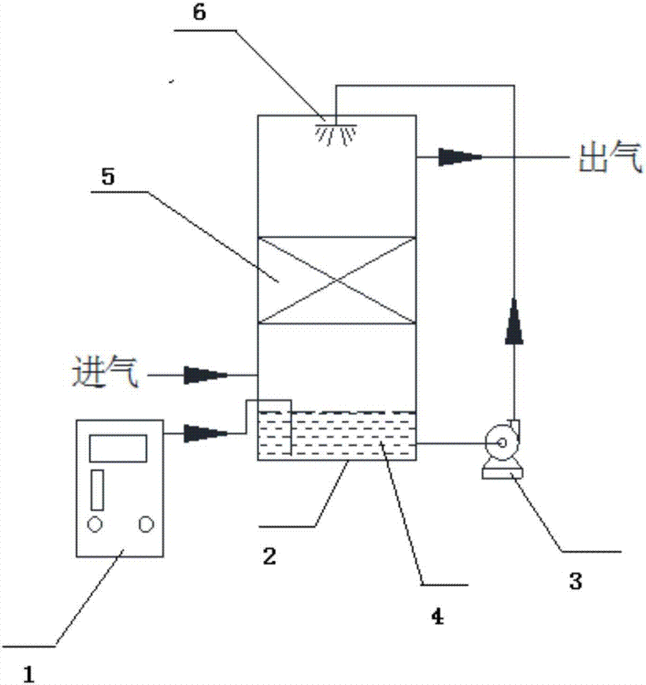
[0028] A three-phase catalytic deodorization system for RTO exhaust gas, including a flue gas cooling tower, a three-phase catalytic deodorization device and connecting pipes; the three-phase catalytic deodorization device is mainly composed of an ozone generator 1, a main reaction tower 2, a circulation pump 3 and Composed of connecting pipes and valves; the bottom of the main reaction tower 2 is a liquid storage tank 4, and the ozone generator 1 is connected to the liquid storage tank 4 at the bottom of the main reaction tower through pipes; the flue gas inlet of the main reaction tower 2 is set in the liquid storage tank 4 above; the middle part of the main reaction tower is a catalytic reaction zone 5 filled with solid-phase catalyst, and a spray device 6 is arranged directly above the top of the main reaction tower, and the liquid inlet of the spray device is connected with the liquid storage tank through a circulating pump 3 and a pipeline; The top side of the reaction to...
Embodiment 2
[0033] Weigh 10 g of high molecular weight polyferric salt, place in a certain amount of deionized water, stir and sonicate for 20 minutes. Then add 1.8755g manganese acetate dissolved in the above solution and keep stirring, then slowly add 10molKMnO 4 solution, the temperature was controlled at 75°C for 45 minutes. After the reaction is completed, filter, wash repeatedly with deionized water for 5-6 times, and then put it into a vacuum oven for drying to obtain MnO with a mass fraction of 10%. 2 / High molecular polymer iron salt catalyst.
Embodiment 3
[0035] Weigh 2.5gFeCl 3 , add deionized water to dissolve, 7.5gAl 2 o 3 Powder (through 60 mesh sieve) add FeCl 3The solution was stirred for 8 small tests, and the solution was evaporated to dryness in a water bath at 85°C, and then put into a vacuum drying oven to dry at 120°C for 12 hours. After grinding, put it into a muffle furnace and bake it at 600°C for 6 hours to make Fe / Al 2 o 3 . Then load Mn by co-precipitation method: Weigh Fe / Al with a mass ratio of 3:4 2 o 3 and manganese acetate, add deionized water to dissolve, and stir for 18 hours. Then slowly add concentrated ammonia water during continuous stirring until the pH of the solution is 12, stir for 1.5 hours, and then filter with suction. Then put it into a vacuum drying oven to dry at 120°C for 12h. Grind after drying, put it into a muffle furnace and bake at 550°C for 4 hours to obtain Fe-Mn / Al 2 o 3 Catalyst, where Fe loading is 2% and Mn loading is 1%.
PUM
| Property | Measurement | Unit |
|---|---|---|
| quality score | aaaaa | aaaaa |
Abstract
Description
Claims
Application Information
 - R&D
- Intellectual Property
- Life Sciences
- Materials
- Tech Scout
- Unparalleled Data Quality
- Higher Quality Content
- 60% Fewer Hallucinations
Browse by: Latest US Patents, China's latest patents, Technical Efficacy Thesaurus, Application Domain, Technology Topic, Popular Technical Reports.
© 2025 PatSnap. All rights reserved.Legal|Privacy policy|Modern Slavery Act Transparency Statement|Sitemap|About US| Contact US: help@patsnap.com