High-flux drug detection micro-fluidic chip and application

A microfluidic chip, high-throughput technology, applied in biological testing, material inspection products, laboratory containers, etc., can solve the problem of large sample demand, achieve good detection results, and achieve high-throughput and fast results Detection analysis, the effect of strong adsorption capacity

Pending Publication Date: 2017-09-29
ZHEJIANG UNIV +1
5 Cites 2 Cited by

AI-Extracted Technical Summary

Problems solved by technology

Although the colloidal gold test paper detection method can be used for rapid on-site detection, a single test paper can only detect a single sample and a single drug...

Abstract

The invention provides a high-flux drug detection micro-fluidic chip. The high-flux drug detection micro-fluidic chip consists of a substrate layer, a modification layer and a reaction layer, wherein the reaction layer consists of n reaction modules; each reaction module consists of an entrance, a reaction channel and an outlet. The chip modified by polylysine is hydrophilic, facilitates a sample to be detected to flow into the chip, and has an adsorption effect on drug complete antigens; the polylysine of the modification layer is matched with PDMS (Polydimethylsiloxane) of the reaction layer, so that the hydrophilic feature of the polylysine can be combined with the high-protein adsorption feature of the PDMS to achieve a better detection effect; detection of different samples occurs in different reaction channels, so that the phenomenon of mutual interference is avoided, and non-specific adsorption is lowered; a single chip is provided with a plurality of reaction modules to realize high-flux rapid result detection and analysis; the sizes, intervals and number of the reaction modules can be adjusted as required to realize simultaneous field detection of a plurality of samples and drugs, so that different detection requirements are met.

Application Domain

Technology Topic

Image

  • High-flux drug detection micro-fluidic chip and application
  • High-flux drug detection micro-fluidic chip and application
  • High-flux drug detection micro-fluidic chip and application

Examples

  • Experimental program(6)

Example Embodiment

[0023] Example 1 Fabrication of chips
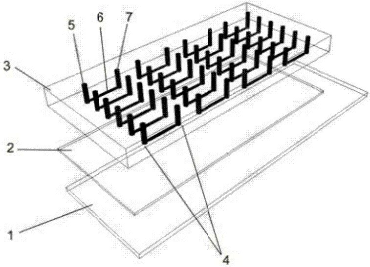
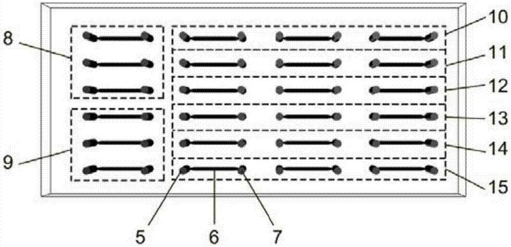
[0024] see figure 1 , a microfluidic chip that can realize high-throughput drug detection. It consists of a substrate layer 1, a modification layer 2, and a reaction layer 3. The reaction layer 3 consists of 24 identical reaction modules 4. Each reaction module 4 consists of The inlet 5, the reaction channel 6 and the outlet 7 are constituted.
[0025] The substrate layer 1 and the modification layer 2 use commercially available glass slides that have been coated with polylysine, preferably with a thickness of 1 mm, a width of 25 mm, and a length of 77 mm.
[0026] The reaction layer 3 adopts PDMS as a material, adopts multi-layer soft lithography technology to make a mold with a micro-channel structure, and pours PDMS with breathable properties on the mold to cure and release the mold. The thickness of the reaction layer 3 can be adjusted according to actual needs, preferably 3-5mm.
[0027] After the reaction layer 3 is made, punch holes at the inlet 5 and outlet 7 with a hole punch with a diameter of 1 mm, and then use a mixed solution of toluene and PDMS to coat the bottom surface of the plasma-treated reaction layer 3, and seal it with the modification layer 2. After connecting, heat to firm at 85°C.

Example Embodiment

[0028] Example 2 Preparation of the standard curve for the detection of methamphetamine (see figure 2 )
[0029] (1) Dilute the complete methamphetamine antigen to 200 μg/mL with 0.01 mol/L, pH7.4 phosphate buffered saline (PBS), and use a pipette to add 3 μL from each inlet 5 into the reaction channel 6 . The 3 reaction modules in the negative control area 8 were only fed with PBS. The chips were dried at 37°C overnight.
[0030] (2) Tween-20 with a volume fraction of 0.05% was added to PBS to prepare a PBST coating solution. Pipette 3 μL of coating solution from each inlet 5 into reaction channel 6. The chips were placed in a wet box and kept at 37°C for 1 h.
[0031] (3) 15 μL of PBST was added to each inlet 5 , and the PBST was drawn out from the outlet 7 using a syringe pump with a pulling function.
[0032] (4) Use PBST to prepare 2.4 μg/mL fluorescent latex microsphere solution with methamphetamine antibody.
[0033] (5) Use the mixture prepared in (4) to serially dilute the methamphetamine standard to the concentration of 3000ng/mL, 1000ng/mL, 750ng/mL, 500ng/mL, 250ng/mL and 100ng/mL.
[0034] (6) Add the methamphetamine sample obtained in (5) to the inlet 5, and pump it into the reaction channel 6 from the outlet 7 through a syringe pump. The 6 reaction modules in the negative control area 8 and the positive control area 9 only pass the latex microsphere solution with methamphetamine antibody. Area 10 was injected with 3000ng/mL methamphetamine, 11 with 1000ng/mL methamphetamine, 12 with 750ng/mL methamphetamine, 13 with 500ng/mL methamphetamine, and 14 with 500ng/mL methamphetamine. The concentration of 250 ng/mL of methamphetamine was administered, and the concentration of 100 ng/mL of methamphetamine was administered to area 15. The chips were placed in a wet box and kept at room temperature for 1 h.
[0035] (7) 15 μL of PBST was added to each inlet 5, and the rinsing was completed by drawing out from the outlet 7 using a syringe pump.
[0036] (8) Use an ultraviolet gel imager to photograph the results of the chip, and then collect the fluorescence intensity of each channel to analyze the results. As the methamphetamine content increased, the fluorescence intensity decreased, resulting in a standard curve. Test results such as image 3 shown.

Example Embodiment

[0037] Example 3 Ice drug detection
[0038](1) Dilute the complete methamphetamine antigen to 200 μg/mL with 0.01 mol/L PBS with pH 7.4, and use a pipette to add 3 μL from each inlet 5 into the reaction channel 6. The chips were dried at 37°C overnight.
[0039] (2) Tween-20 with a volume fraction of 0.05% was added to PBS to prepare a PBST coating solution. Pipette 3 μL of coating solution from each inlet 5 into reaction channel 6. The chips were placed in a wet box and kept at 37°C for 1 h.
[0040] (3) 15 μL of PBST was added to each inlet 5 , and the PBST was drawn out from the outlet 7 using a syringe pump with a pulling function.
[0041] (4) Use PBST to prepare 2.4 μg/mL fluorescent latex microsphere solution with methamphetamine antibody.
[0042] (5) Use the mixture prepared in (4) to mix with the methamphetamine sample.
[0043] (6) Add the methamphetamine sample obtained in (5) to the inlet 5, and pump it into the reaction channel 6 from the outlet 7 through a syringe pump. The chips were placed in a wet box and kept at room temperature for 1 h.
[0044] (7) 15 μL of PBST was added to each inlet 5, and the rinsing was completed by drawing out from the outlet 7 using a syringe pump.
[0045] (8) Use an ultraviolet gel imager to photograph the results of the chip, and then collect the fluorescence intensity of each channel to analyze the results. In the absence of methamphetamine, the fluorescence intensity will be the strongest, while the presence of methamphetamine reduces the fluorescence intensity. By comparing with the standard curve, the detection result can be obtained.

PUM

PropertyMeasurementUnit
Length77.0mm
Width25.0mm
Thickness1.0mm
tensileMPa
Particle sizePa
strength10

Description & Claims & Application Information

We can also present the details of the Description, Claims and Application information to help users get a comprehensive understanding of the technical details of the patent, such as background art, summary of invention, brief description of drawings, description of embodiments, and other original content. On the other hand, users can also determine the specific scope of protection of the technology through the list of claims; as well as understand the changes in the life cycle of the technology with the presentation of the patent timeline. Login to view more.

Similar technology patents

Classification and recommendation of technical efficacy words

  • Strong adsorption capacity
  • Good detection effect

Passive positioning and identification system for civil unmanned aerial vehicles

ActiveCN107678023AGood ability to detect low-altitude, slow-moving and small targetsGood detection effectRadio wave reradiation/reflectionTelemetry EquipmentLow altitude
Owner:芜湖华创光电科技有限公司
Why Eureka
Try Eureka