
Efficient zinc powder production device

A production equipment and zinc powder technology, applied in the field of high-efficiency zinc powder production equipment, can solve the problems of cumbersome feeding and discharging process, reduce processing production efficiency, reduce cooling efficiency, etc., achieve easy disassembly and maintenance, improve production and processing efficiency, The effect of reducing production costs

Pending Publication Date: 2017-11-17
贵州明峰工业废渣综合回收再利用有限公司
View PDF12 Cites 2 Cited by
  • Summary
  • Abstract
  • Description
  • Claims
  • Application Information

AI Technical Summary

Problems solved by technology

[0006] There is an anode device at the conductive bottom of the existing electric arc furnace. After the bottom refractory lining is corroded by the molten metal, the anode plate is melted and the bottom of the furnace is penetrated, resulting in a slag leakage accident at the bottom of the furnace; at the same time, there are many conductive steel plates at the bottom of the furnace, and it is necessary to open multiple long openings on the bottom steel plate. To connect the lead-out copper bars, it is necessary to design a special ring-shaped reinforced concrete structure foundation for the bottom of the furnace, which greatly increases the cost of the electric furnace and the construction period
[0007] Due to the fast production and processing speed of electric furnace zinc smelting, the consumption of ore raw materials and reducing agents in the electric arc furnace is relatively fast. In the process of zinc smelting, it is necessary to frequently add raw materials to the electric arc furnace. The operation is cumbersome, and it usually needs to be shut down to add materials, which not only reduces the efficiency of processing and production, but also has high labor costs; and in the production process, the speed of heating up after raw materials are added to the electric zinc furnace is slow, and it takes a long time to process The raw material is heated up to the processing temperature, but the operation of preheating the raw material is relatively cumbersome, the equipment structure is complex, the process of feeding and discharging is cumbersome, and the preheating of the raw material is uneven, and the preheating effect is poor.
[0008] During the production and processing of electric furnace zinc smelting, the temperature of the zinc vapor generated by the electric arc furnace is relatively high, and it is difficult to cool it in time during the production process. The parts inside the dust device will affect the service life of the production equipment and affect the production quality, and cause the production equipment to be scrapped, increase maintenance costs, delay production progress, and cause production losses; most of the current condensers used are snakes. The structure of the serpentine cooling pipe, because there are many bends in the serpentine cooling pipe, zinc vapor is easy to deposit in the bend of the serpentine cooling pipe during the condensation process, which will not only affect the flow rate of the airflow, reduce the cooling efficiency, but also be easy to block Cooling pipe; if the cooling pipe is blocked, the heat carried by the zinc vapor cannot be discharged in time, which will easily cause an explosion and cause a greater safety hazard; in order to solve the above problems, the current production process of zinc powder is often shut down for inspection, maintenance and replacement cooling tube, not only the replacement operation is cumbersome, the maintenance cost is high, but also the production efficiency will be reduced, resulting in the overall production of zinc powder is not high
[0009] Since the zinc powder particles formed by the condensation of zinc vapor are small, the condenser cannot completely collect the zinc powder. If the tail gas is directly discharged, it will not only cause waste and affect the zinc powder production, but also the zinc powder particles in the tail gas will easily cause environmental pollution; The current dust collector is not effective in collecting dust during the production of zinc powder. The main reason is that the dust is easily adsorbed on the dust collection bag in the dust collector. When the dust is adsorbed to a certain extent, the dust collection bag absorbs the dust The capacity will be greatly reduced, resulting in the zinc powder dust in the exhaust gas cannot be completely absorbed, the utilization rate of the exhaust gas is low, and it will still cause waste. Higher, and frequent downtime maintenance will shorten the service life of the dust collector; so the existing dust collector has the unstable ability of the dust collection bag to absorb dust, poor dust collection effect, and dust collection efficiency in the process of zinc powder production. Low, low exhaust gas utilization
[0010] Sealed barrels are often used when zinc powder is packaged; the existing sealed barrel packaging equipment has the problems of cumbersome zinc powder filling process, loose dust after zinc powder is poured into the sealed barrel, and cannot For the capping operation, after the filling is completed, manual sealing and capping operations are required, which is not only inefficient and difficult to operate, but also the sealing effect is unstable and easily affects the preservation effect
[0011] Therefore, the existing zinc powder processing equipment has the problems of complex structure and cumbersome processing operations. Not only the degree of mechanization is low, the integrity of the equipment is poor, but also the processing cost is high, the processing efficiency is low, and the product quality is unstable.

Method used


Image

  • Efficient zinc powder production device
  • Efficient zinc powder production device
  • Efficient zinc powder production device

Examples


Embodiment Construction

[0035] The present invention will be further described below in conjunction with the accompanying drawings and embodiments, but not as a basis for limiting the present invention.

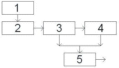
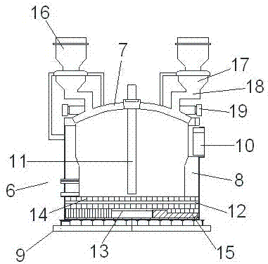
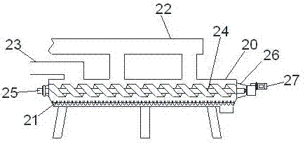
[0036] Example. A high-efficiency zinc powder production equipment, such as Figure 1 to Figure 6 As shown, it includes an automatic feeding electric zinc furnace 2 and a raw material electric heating equipment 1 connected with the automatic feeding electric zinc furnace 2, and also includes a pulse dust collection device 4 connected with the automatic feeding electric zinc furnace 2 through a condenser 3, Condenser 3 and pulse dust collecting device 4 are respectively connected with screening and packaging device 5; described automatic feeding electric zinc furnace 2 comprises electric arc furnace 6 and is arranged on the charging device above electric arc furnace 6, and described electric arc furnace 6 comprises furnace Cover 7, furnace body 8 and furnace bottom electrode 9, the furnace cover 7 i...


PUM


Abstract

The invention discloses an efficient zinc powder production device which comprises an automatic-feeding electric zinc furnace, an electric raw material heating device, a condenser, a pulse dust collection device and a screening and packing apparatus. The automatic-feeding electric zinc furnace comprises an electric-arc furnace and a feeding device, the electric-arc furnace comprises a furnace cover, a furnace body and a furnace bottom electrode, an exhausting port is formed in one side wall of the furnace body, and a cathode is arranged in the furnace body. The furnace bottom electrode comprises a fire-resistant furnace liner, a conductive flow equalizing plate is arranged below the fire-resistant furnace liner, a group of anode plates are arranged on the fire-resistant furnace liner, the lower portions of the anode plates penetrate through the fire-resistant furnace liner to be connected with the conductive flow equalizing plate, and one side of the conductive flow equalizing plate is connected with a conductive cast steel rod. The feeding device comprises a containing cylinder, a feeding hopper, a feeding pipe and a feeding motor arranged on one side of the feeding pipe. The efficient zinc powder production device has the advantages of being higher in mechanical automatic degree, stronger in integrality and high in zinc powder producing and processing efficiency, the processing cost is reduced, the producing and processing efficiency is improved, and the product quality is improved.

Description

technical field [0001] The invention relates to an industrialized zinc smelting device, in particular to high-efficiency zinc powder production equipment. Background technique [0002] Electric furnace zinc smelting uses electric energy as the heat source. In the presence of reducing agents such as coke or coal, the charge is directly heated to continuously reduce the ZnO component in it to zinc vapor and condense into metallic zinc. This process can handle high-copper and high-iron-zinc ores. [0003] In the 1930s, electric furnace zinc smelting technology appeared abroad. In the 1980s, China began to adopt electric furnace zinc smelting technology, and it has been popularized and applied in many pyro-method zinc smelting plants, and the production scale is relatively considerable. [0004] The electric furnace zinc smelting is mainly through electric arc furnace power supply heating, so that the raw materials in the furnace react under the action of electric heat energy ...

Claims


Application Information

Patent Timeline
IPC IPC(8): C22B19/04B22F9/12
CPCC22B19/04B22F9/12Y02P10/20
Inventor 石运明容敏贲仕胜
Owner 贵州明峰工业废渣综合回收再利用有限公司
Learn More