Pulse ultrasonic sound field detection device and method
A detection device, pulsed ultrasonic technology, applied to measuring devices, measuring ultrasonic/sonic/infrasonic, instruments, etc., can solve problems such as narrow application range, sound field interference, sound pressure and phase quantitative measurement that cannot be used in the sound field, and reach the frequency range wide range, lower detection cost, and high spatial resolution
- Summary
- Abstract
- Description
- Claims
- Application Information
AI Technical Summary
Problems solved by technology
Method used
Image
Examples
Embodiment 1
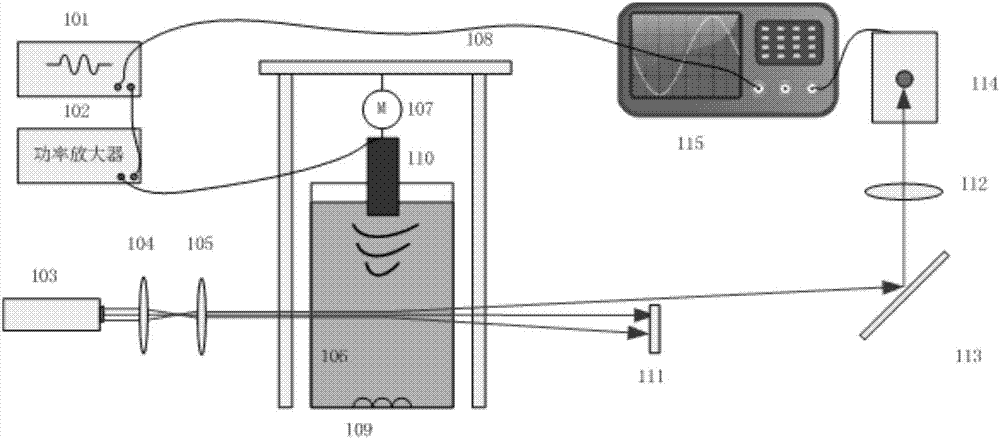
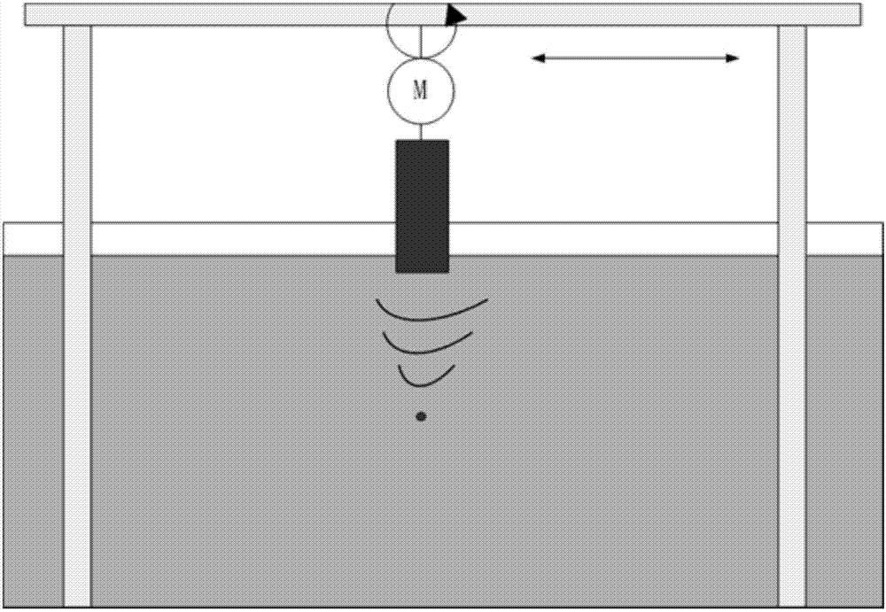
[0052] A pulse ultrasonic sound field detection device, see figure 1 and figure 2 , the detection device includes: a signal generator 101, a power amplifier 102, a He-Ne (helium-neon) laser 103, a first convex lens 104, a second convex lens 105, a water tank 106, a stepping motor 107, a displacement platform 108, a sound-absorbing Material 109 , ultrasonic probe 110 , light shielding plate 111 , third convex lens 112 , mirror 113 , photodetector 114 , and oscilloscope 115 .
[0053] The signal generator 101 is connected to the power amplifier 102 , and the output signal is connected to the ultrasonic probe 110 . The signal generator 101 is used to generate an ultrasonic excitation signal. When the excitation signal is a periodic pulse, the ultrasonic probe 110 outputs pulsed ultrasonic waves. The power amplifier 102 is used to amplify the excitation signal to drive the ultrasonic probe 110 , and the ultrasonic probe 110 generates a pulsed sound field in the water tank 106 ....
Embodiment 2
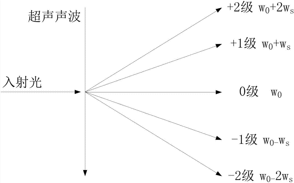
[0059] A kind of pulse ultrasonic sound field detection method, see image 3 and Figure 4 , the detection method is based on the pulsed ultrasonic sound field detection device in embodiment 1, and the detection method comprises the following steps:
[0060] Ultrasonic wave is a kind of elastic wave. When propagating in the medium, the density of the medium will change, and then the refractive index of the medium will change periodically, forming an ultrasonic grating. When the laser light passes through the ultrasonic grating, the phase of the laser light is spatially modulated and diffracted.
[0061] According to the following formula:
[0062]
[0063] Among them, L 0 is the characteristic length of light diffracted by ultrasonic waves, λ s is the wavelength of ultrasonic waves in the medium, and λ is the wavelength of light in the medium. When the ultrasonic surface width L satisfies:
[0064] L≤L 0 / twenty two)
[0065] Laser light will undergo Raman-Ness diff...
Embodiment 3
[0092] Combined with the specific experimental equipment, Figure 5-Figure 6 The scheme in embodiment 1 and 2 is carried out feasibility verification, see the following description for details:
[0093] The device parameters used in the present embodiment are: 633um He-Ne laser 103, 10MHz ultrasonic probe 110, the probe diameter is 10mm, the liquid in the water tank 106 is pure water, the wavelength range of photodetector 114 is 400-1000um, and the bandwidth is 400MHz, the focal length of the first convex lens 104 and the second convex lens 105 is 30mm, and the focal length of the third convex lens is 50mm. The center frequency of the excitation pulse of the signal generator 101 is 10MHz, the number of pulses is 10, and the signal amplitude is 400mV p-p , the amplification factor of the power amplifier 102 is 32dB. The obtained one-dimensional sound field and two-dimensional sound field sound pressure distribution are as follows: Figure 5 As shown, through the simulation c...
PUM
 Abstract
Description
Claims
Application Information
 - R&D
- Intellectual Property
- Life Sciences
- Materials
- Tech Scout
- Unparalleled Data Quality
- Higher Quality Content
- 60% Fewer Hallucinations
Browse by: Latest US Patents, China's latest patents, Technical Efficacy Thesaurus, Application Domain, Technology Topic, Popular Technical Reports.
© 2025 PatSnap. All rights reserved.Legal|Privacy policy|Modern Slavery Act Transparency Statement|Sitemap|About US| Contact US: help@patsnap.com


