Self-maintaining incineration system for sludge and working method

A self-sustaining incineration and sludge technology, applied in the field of pollutant treatment, can solve the problems of increasing dust removal and flue gas purification load, reducing boiler efficiency, reducing furnace temperature and ash softening point, etc., achieving high heat utilization efficiency and meeting national standards The effect of emissions

Inactive Publication Date: 2017-12-01
张国闽
View PDF4 Cites 7 Cited by
  • Summary
  • Abstract
  • Description
  • Claims
  • Application Information

AI Technical Summary

Problems solved by technology

Due to the high moisture content and low calorific value of sludge, most of the domestic sludge can only be used as co-combustion materials for co-processing with waste incineration power plants, cement kilns and coal-fired power plants, but the amount of sludge co-combustion is limited , and sludge blending will reduce the temperature in the furnace and the softening point of ash, and increase the amount of fly ash produced, increase the load of dust removal and flue gas purification, and reduce boiler efficiency and other disadvantages

Method used


Image

  • Self-maintaining incineration system for sludge and working method

Examples


Embodiment Construction

[0028] The present invention will be further described below in conjunction with the accompanying drawings.

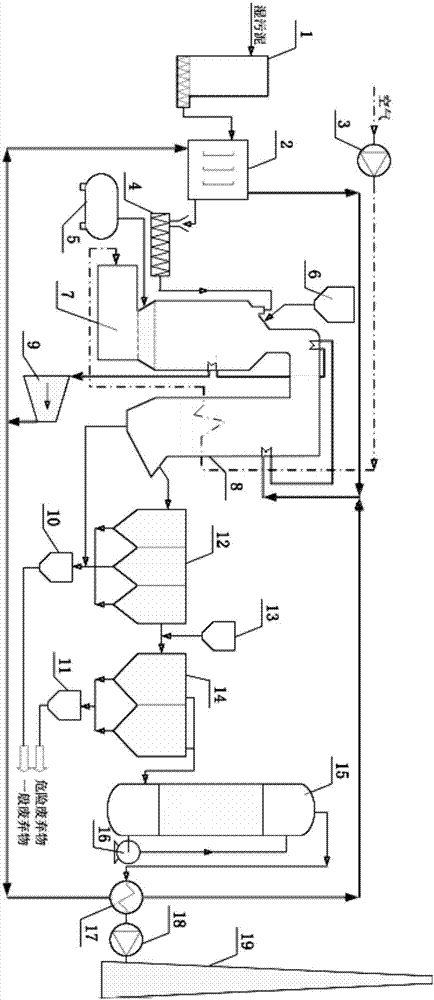
[0029] as attached figure 1 The sludge self-sustaining incineration system shown includes storage and transportation system, semi-drying system, incineration and waste heat boiler system, steam turbine power generation system, flue gas treatment system, ash treatment system and flue gas discharge system from front to back. In the accompanying drawings, solid arrows with solid lines indicate steam pipelines, hollow arrows with dotted lines indicate air pipelines, and hollow arrows with solid lines indicate material pipelines.

[0030] The storage and delivery system includes a wet sludge storage bin 1 and a screw conveyor at the bottom of the wet sludge storage bin 1; the screw conveyor gradually pushes the wet sludge in the wet sludge storage bin 1 to the semi-drying system .

[0031] The semi-drying system includes a sludge dryer 2 and a second screw conveyor 4. The...


PUM


Abstract

The invention discloses a self-maintaining incineration system for sludge and a working method. The self-maintaining incineration system for the sludge comprises a storing and conveying system, a semi-desiccation system, an incineration and waste heat boiler system, a turbine power generation system, a flue gas treatment system and an ash slag treatment system; the semi-desiccation system comprises a sludge desiccation machine; the incineration and waste heat boiler system comprises an incinerator and a waste heat boiler; and the turbine power generation system comprises a turbine power generator and a steam circulating pipeline, wherein the steam circulating pipeline comprises closed-loop circulating pipelines which sequentially connect the turbine power generator, the sludge desiccation machine and the incineration and waste heat boiler system in series. The working method of the system comprises the steps that power generation is conducted through heat generated through incineration, and desiccation operation is conducted on the wet sludge through the semi-desiccation system. Therefore, the high heat utilization efficiency is achieved through cooperation of the whole desiccation, incineration and waste heat utilization system and the using method thereof, self-maintaining incineration of the sludge can be achieved without adding external energy, the yearly running time reaches 8,000 h, and outlet flue gas is exhausted in the manner of meeting the national standard.

Description

technical field [0001] The invention relates to the field of pollutant treatment, in particular to a sludge self-sustaining incineration system and working method. Background technique [0002] For a long time, the tendency of "heavy water and light sludge" has prevailed in my country's sewage treatment industry, leaving many sludge treatment and disposal problems. Sludge, as the remaining product of sewage treatment, is a high-moisture sediment produced in the process of sewage treatment. It is an aggregate composed of a variety of microbial bacteria micelles and their adsorbed organic and inorganic substances. Sludge contains toxic and harmful substances such as heavy metals, pathogenic bacteria, parasites and refractory substances, which seriously threaten the safety of human beings and the ecological environment. If the sludge is not treated scientifically and rationally, it is easy to cause secondary pollution. At present, sludge treatment and disposal has become the ...

Claims


Application Information

Patent Timeline
Patent Type & Authority Applications(China)
IPC IPC(8): F23G7/00F23G7/06F23J15/00F23J15/02F23J15/04
CPCY02E20/12F23G7/001F23G7/06F23G2201/10F23G2204/103F23G2206/10F23G2206/20F23G2209/12F23G2209/14F23J15/006F23J15/025F23J15/04F23J2215/10F23J2215/301F23J2215/60F23J2217/101F23J2217/102F23J2217/50F23J2219/20F23J2219/30F23J2219/40
Inventor 张国闽魏伟胡明宋祖威刘龙
Owner 张国闽
Why Eureka
Try Eureka