
Integrated biochemical sensor based on rib optical waveguide

A biochemical sensor and optical waveguide technology, applied in the field of optical biochemical sensing, can solve the problems of unfavorable integration of on-chip systems, large overall size, long interference structure, etc., and achieve the effects of high detection sensitivity, low cost, and easy processing

Inactive Publication Date: 2017-12-15
SHENZHEN GRADUATE SCHOOL TSINGHUA UNIV
View PDF4 Cites 13 Cited by
  • Summary
  • Abstract
  • Description
  • Claims
  • Application Information

AI Technical Summary

Problems solved by technology

[0003] Most integrated biochemical sensors have long interferometric structures, low coupling efficiency, and are not easy to integrate
In general, in order to reduce radiation loss, MZI sensors adopt a small-angle Y-shaped branch structure. In order to obtain ideal phase modulation results, a large overall size is required; sub-micron waveguide MZI sensors usually require grating coupling, which cannot be directly Using end-face coupling, the coupling efficiency is low; when the waveguide is in contact with the sample, it is usually directly soaked, which is not conducive to the integration of the system on chip

Method used


Image

  • Integrated biochemical sensor based on rib optical waveguide
  • Integrated biochemical sensor based on rib optical waveguide
  • Integrated biochemical sensor based on rib optical waveguide

Examples


example 1

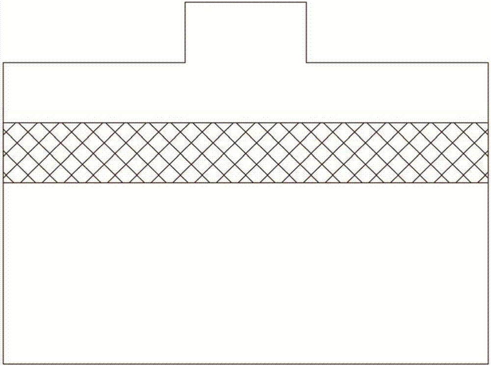
[0044] A silicon-on-insulator (SOI) with a silicon thickness of 10 μm on the top layer, a silicon oxide thickness of 2 μm on the insulating layer, and a silicon-on-insulator (SOI) thickness of 475 μm was selected as the manufacturing material. Ridge waveguide and air groove structures were obtained by deep ultraviolet exposure and inductively coupled plasma dry etching. Such as Figure 4 As shown, the real-time protein solution concentration detection system is composed of a tunable laser at the input end and a single-mode optical fiber. After calibration, the photodetector is used to measure the intensity of the outgoing light to test the protein concentration of the sample.

example 2

[0046] Such as Figure 5 As shown, the above detection system is arrayed, with multiple integrated biochemical sensors (MZI sensor 1, MZI sensor 2, MZI sensor 3...MZI sensor n); monochromatic lasers can be used instead of tunable lasers, and a variety of wavelength of light λ 1 , lambda 2 , lambda 3 ... λ n . At the same time, a plurality of photodetectors PD1, PD2, PD3...PDn are used together. Through the array of the detection system, the measurement of the emitted light intensity of the analyte is realized, and the quantitative analysis of the solution change is carried out.


PUM

PropertyMeasurementUnit
Thicknessaaaaaaaaaa
Thicknessaaaaaaaaaa
Thicknessaaaaaaaaaa

Abstract

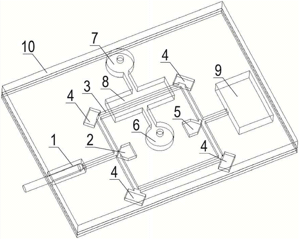
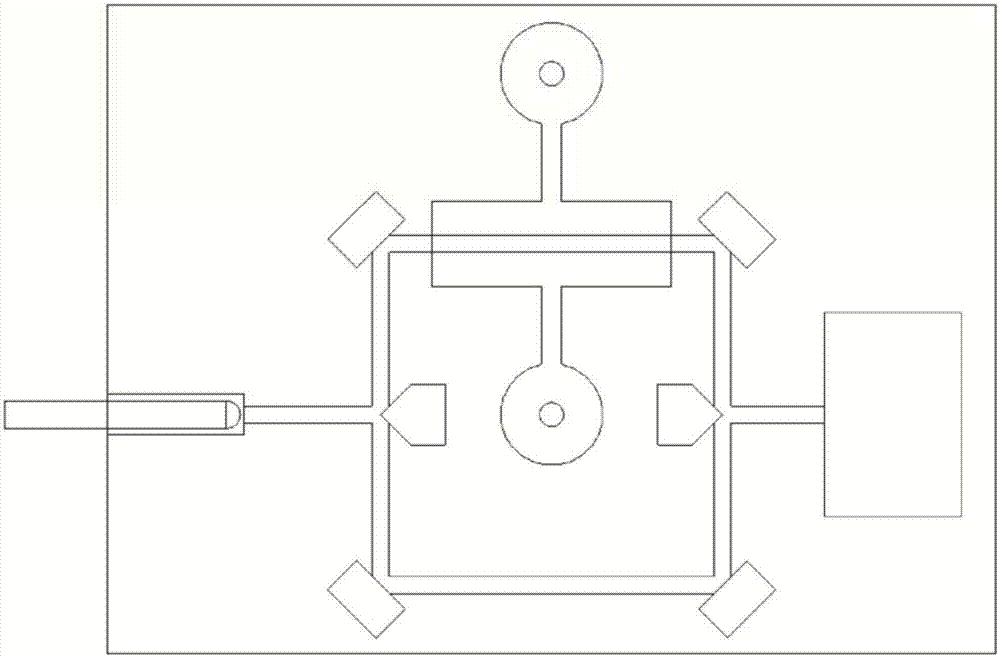
An integrated biochemical sensor based on rib optical waveguide comprises an MZI (Mach-Zehnder interferometer) detection chip, an optical fiber support, a plurality of polymer cavities and a micro-channel system which are machined on the same SOI (silicon on insulator) silicon wafer as well as photoelectric detector and a detection circuit which are arranged in the polymer cavities. The MZI detection chip comprises the rib optical waveguide, a medium groove, a sample pool, a medium groove beam splitter and a medium groove beam combiner. Optical fiber is coupled with the rib optical waveguide, and the rib optical waveguide is coupled to the photoelectrical detector and the detection circuit. Light transmitted by an input end of the rib optical waveguide is split into two branch light beams by the medium groove beam splitter, the two branch light beams are transmitted along two waveguide arms respectively, one waveguide arm is coupled to the sample pool, the light beam of the waveguide arm is subjected to phase modulation by a sample in the sample pool, the two light beams are combined into an output light beam by the medium groove beam combiner, the photoelectric detector and the detection circuit detect change of light intensity and convert the output light beam into an electrical signal, and the sample in the sample pool is detected. The sensor is easy to machine, compact in structure, high in sensitivity and low in cost.

Description

technical field [0001] The invention relates to the technical field of optical biochemical sensing, in particular to an integrated biochemical sensor based on a ridge optical waveguide. Background technique [0002] With the rapid development of science and technology and the continuous penetration of advanced technologies in related disciplines into the field of biomedicine, the development of biomedical testing technology has become increasingly polarized. On the one hand, various large-scale automated, high-performance, and high-efficiency instruments and equipment have come out one after another, which has greatly improved the work efficiency of laboratory analysis and testing; on the other hand, the miniaturization, portability, easy operation, and timely results of experimental instruments Accuracy, and a new biomedical testing model based on it, namely Point of Care Testing (POCT). [0003] Most integrated biochemical sensors have long interferometric structures, low...

Claims


Application Information

Patent Timeline
IPC IPC(8): G01N21/45
CPCG01N21/45G01N2021/458
Inventor 董瑛刘跃明王玺王晓浩
Owner SHENZHEN GRADUATE SCHOOL TSINGHUA UNIV
Learn More