ZnO-mixed cathode buffer layer-based organic solar battery and preparation method thereof

A cathode buffer layer and solar cell technology, applied in circuits, photovoltaic power generation, electrical components, etc., can solve problems such as low photoelectric conversion efficiency, rough surface, and large gaps in the cathode layer, so as to improve electron transmission capacity and reduce surface roughness , the effect of increasing the photocurrent density

Inactive Publication Date: 2018-01-09
UNIV OF ELECTRONICS SCI & TECH OF CHINA
View PDF3 Cites 8 Cited by
  • Summary
  • Abstract
  • Description
  • Claims
  • Application Information

AI Technical Summary

Problems solved by technology

[0005] Based on the above technical problems, the present invention provides an organic solar cell based on a mixed ZnO cathode buffer layer, thereby solving the technical problems of large gaps, rough surface and low photoelectric conversion efficiency of the conventional organic solar cell cathode layer; meanwhile, the present invention also The preparation method of the organic solar cell is disclosed

Method used


Image

  • ZnO-mixed cathode buffer layer-based organic solar battery and preparation method thereof
  • ZnO-mixed cathode buffer layer-based organic solar battery and preparation method thereof

Examples


Embodiment

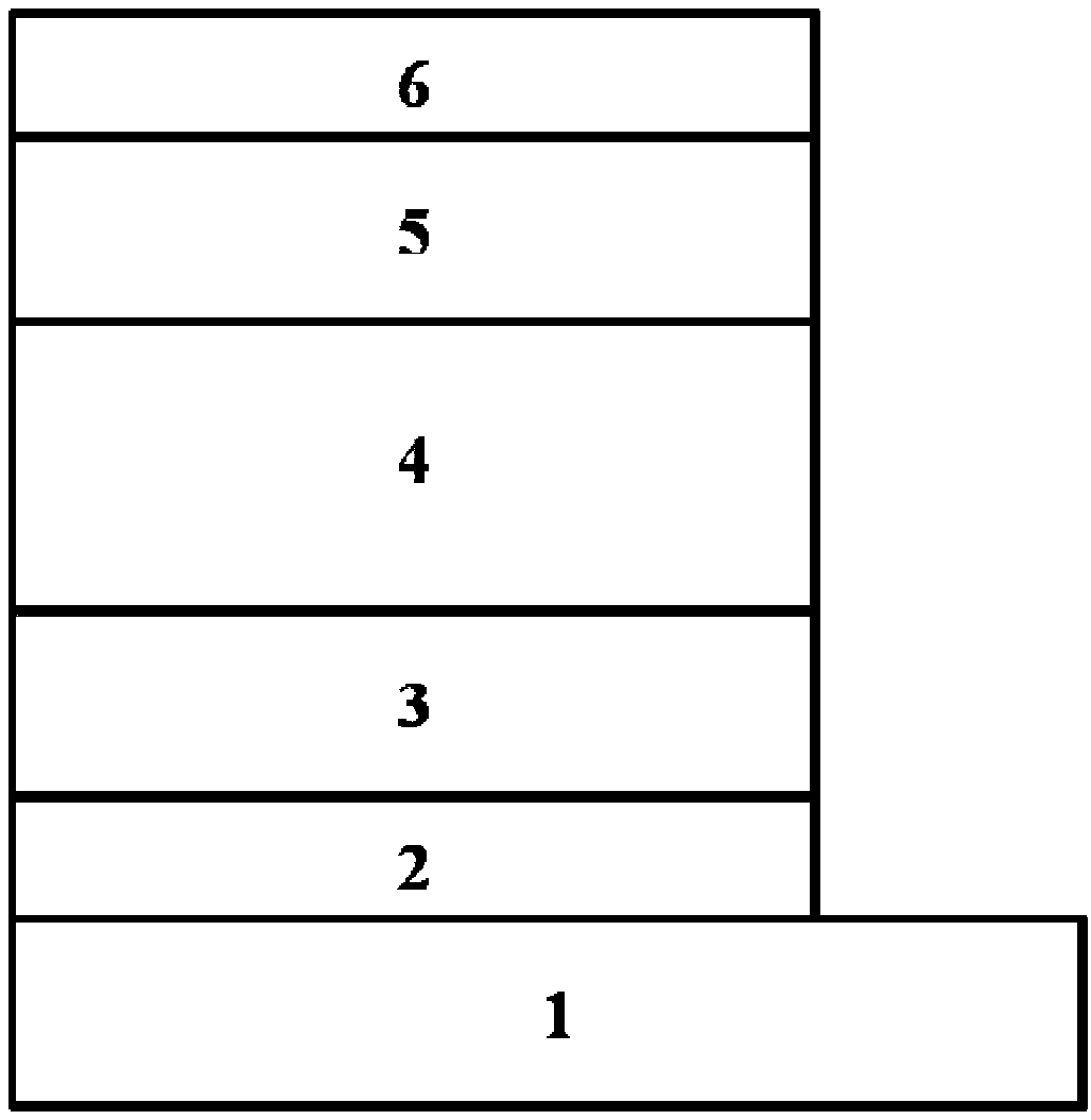
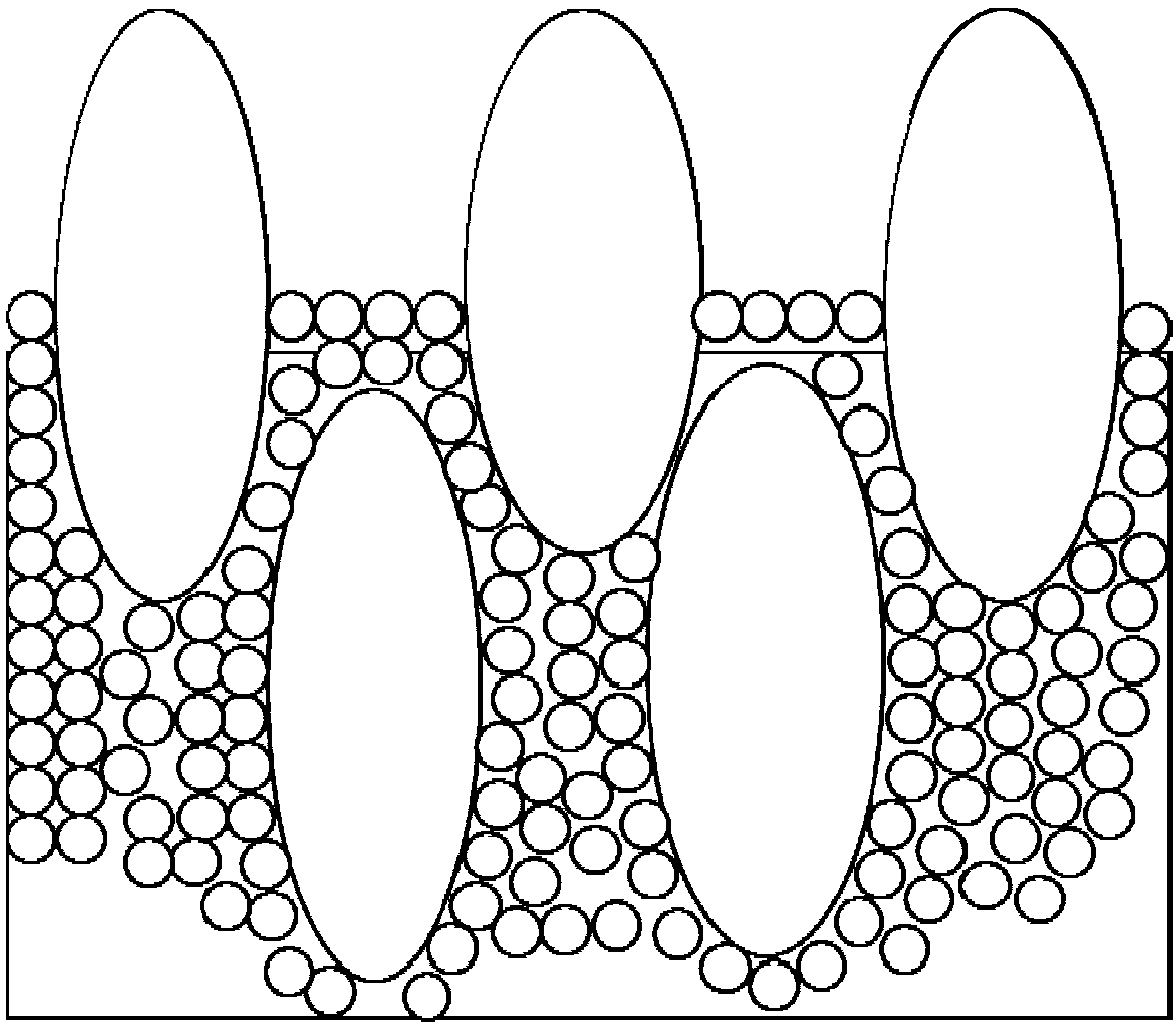
[0045] Such as figure 1 , figure 2 As shown, an organic solar cell based on a mixed ZnO cathode buffer layer adopts an inverted structure, including a substrate layer 1, a transparent conductive cathode layer 2, a cathode buffer layer 3, and a photoactive Layer 4, anode buffer layer 5 and metal anode layer 6;

[0046] in,

[0047] The cathode buffer layer 3 is a solid film formed by mixing a ZnO nanoparticle dispersion and a ZnO precursor solution prepared by a sol-gel method in a certain proportion, and forming after thermal annealing;

[0048] In the mixed solution, the mass percent ratios of the ZnO nanoparticle dispersion and the ZnO precursor solution are respectively:

[0049] ZnO nanoparticles 80% to 98%;

[0050] ZnO precursor 2% to 20%;

[0051] The thickness range of the cathode buffer layer 3 is 220-380nm.

[0052] Preferably, the thickness of the photoactive layer 4 is 50-300nm, mainly composed of electron donor material PTB7-TH and electron acceptor materia...

specific Embodiment

[0073] Control group 1

[0074] Clean the substrate composed of a transparent substrate layer 1 and a transparent conductive cathode layer 2 composed of ITO with a surface roughness less than 1 nm, and dry it with nitrogen after cleaning; spin-coat the ZnO nanoparticle dispersion on the surface of the transparent conductive cathode ITO (Working parameters: rotating speed 4000rpm, time 40s, thickness 300nm, the same below, no further explanation) Prepare the cathode buffer layer 3, and prepare PTB7-TH:PC on the cathode buffer layer 3 by spin coating 71 BM (mass ratio 1:1.5, concentration 25mg / ml, the same below, no longer elaborated) photoactive layer 4 (1200rpm, 90s, 120nm), vapor-deposited anode buffer layer 5MoO3 (thickness 15nm) on the photoactive layer 4 surface; Metal anode Ag (thickness: 100 nm) is vapor-deposited on the anode buffer layer 5 . Under standard test conditions: air quality AM 1.5, light intensity 100mW / cm 2 , the open circuit voltage of the device was mea...


PUM


Abstract

The invention relates to a ZnO-mixed cathode buffer layer-based organic solar battery. An inversion structure is adopted by the organic solar battery; the organic solar battery comprises a substrate layer, a transparent conductive cathode layer, a cathode buffer layer, a photoactive layer, an anode buffer layer and a metal anode layer which are sequentially arranged from bottom to top; and the cathode buffer layer is a solid thin film which is formed by mixing a ZnO nano-particle dispersion liquid and a ZnO precursor solution prepared through a sol-gel method at a ratio and carrying out thermal annealing. The invention further discloses a preparation method of the battery. The cathode buffer layer is prepared through mixing a certain amount of ZnO precursor solution prepared through the sol-gel method into the large-particle size ZnO nano-particle dispersion liquid, and gaps among ZnO nano-particles can be filled while relatively large contact area of the cathode buffer layer and the photoactive layer is ensured, so that the defect of the cathode buffer layer is reduced and the photoelectric conversion efficiency of a device is effectively improved.

Description

technical field [0001] The invention relates to a solar cell, which belongs to the field of new energy solar cells; in particular, it relates to an organic solar cell based on a mixed ZnO cathode buffer layer; the invention also discloses a preparation method of the organic solar cell. Background technique [0002] With the development of the world economy, energy consumption, environmental pollution and other issues have increasingly become the primary concerns of countries all over the world. Traditional fossil energy has been on the verge of being exhausted with people's continuous development. Solar energy, as a renewable energy source, fits the bill. The energy of solar energy reaching the ground every second is as high as 800,000 kilowatts. If 0.1% of the solar energy on the earth's surface is converted into electrical energy, the conversion rate is 5%, and the annual power generation can reach 5.6×10¹² kilowatts / hour. In the effective use of solar energy, solar photo...

Claims


Application Information

Patent Timeline
Patent Type & Authority Applications(China)
IPC IPC(8): H01L51/44H01L51/48
CPCY02E10/549
Inventor 于军胜范谱郑丁杨根杰
Owner UNIV OF ELECTRONICS SCI & TECH OF CHINA
Why Eureka
Try Eureka