
Novel electrical cabinet

A power cabinet, a new type of technology, applied in the substation/distribution device shell, substation/switchgear cooling/ventilation, coating, etc., can solve the problem of reducing the load-bearing capacity of the partition board, affecting the installation of large equipment in the power cabinet, and reducing the use Life and other issues, to achieve good heat dissipation effect

Active Publication Date: 2018-01-26
国网河南省电力公司南召县供电公司
View PDF10 Cites 5 Cited by
  • Summary
  • Abstract
  • Description
  • Claims
  • Application Information

AI Technical Summary

Problems solved by technology

However, this utility model uses ventilation panels and partition panels to divide the power cabinet into different work areas. On the one hand, it may affect the installation of large-scale equipment in the power cabinet, and on the other hand, it is convenient for the equipment of the power cabinet to be installed above the partition board, and the partition board Air inlet plates and vent holes are also arranged on the top, so that the load-bearing capacity of the partition plate is reduced, thereby reducing the service life of the utility model

Method used


Image

  • Novel electrical cabinet
  • Novel electrical cabinet
  • Novel electrical cabinet

Examples


Embodiment 1

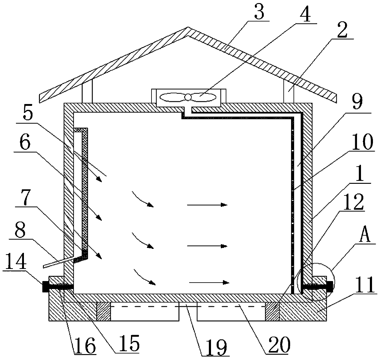
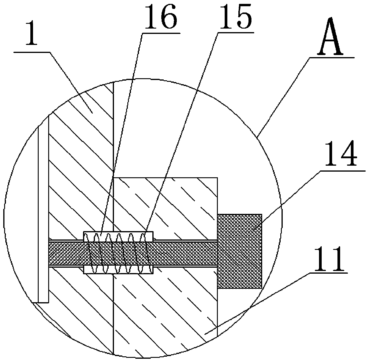
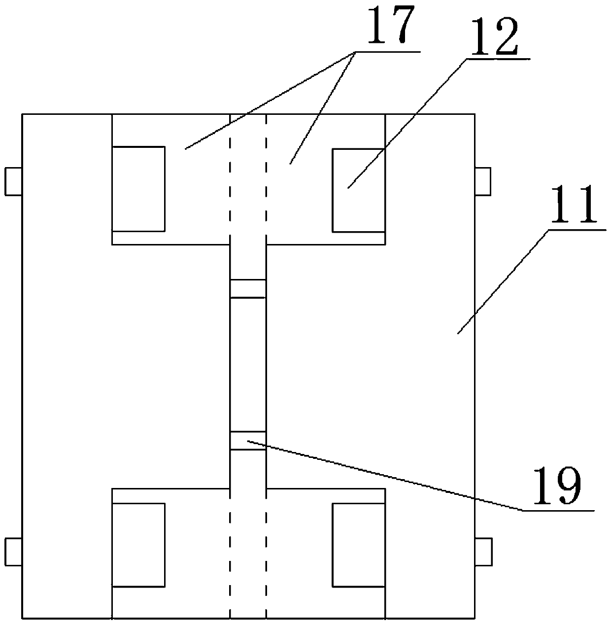
[0033] Such as figure 1 , figure 2 and image 3 As shown, a new type of power cabinet includes a cabinet body 1. The top of the cabinet body 1 is connected to the top cover 3 through the support rod 2. The function of the top cover is mainly to prevent rain and sunscreen; Exhaust fan 4; inwardly inclined ventilation holes 5 are provided on the side wall of the cabinet body, and a filter cover 6 is provided at the corresponding position on the inner wall of the cabinet body 1 and the ventilation hole 5, and a dust accumulation tank 7 is provided at the bottom of the filter cover 1 6, wherein the dust accumulation tank 7 is connected The bottom is provided with a drainage pipe 8, and the drainage pipe 8 passes through the side wall of the cabinet body 1 and extends out of the cabinet.

[0034] The interior of the side wall corresponding to the cabinet 1 and the ventilation hole 5 is provided with an exhaust channel 9. The exhaust channel 9 is a rectangular parallelepiped stru...

Embodiment 2

[0041] Embodiment 2 is basically the same as Embodiment 1, the difference is: as Figure 4 As shown, filter cover 2 18 is set on the top of exhaust fan 4, and is used to filter dust; In addition, waterproof cover 13 is set on the cabinet body 1 outer wall corresponding to ventilation hole 5, and is used to prevent rainwater from entering the cabinet body, which is safer.

[0042] Wherein the outer surface of the cabinet 1 is sprayed with a thermally conductive insulating coating, and the thermally conductive insulating coating is made of the following raw materials in parts by weight: 35 parts of acrylic emulsion, 15 parts of epoxy resin, 5 parts of nano-magnesium oxide, 8 parts of silicon nitride, and 5 parts of rosin powder 12 parts of nitrile rubber powder, 5 parts of polyethylene glycol octyl phenyl ether, 2 parts of sodium lignosulfonate, 20 parts of solvent, 6 parts of water and 3 parts of silicone dispersant.

[0043] The solvent is a mixture of ethylene glycol and xyle...

Embodiment 3

[0046] Embodiment 3 has the same structure as Embodiment 1, the difference is:

[0047] Wherein the outer surface of the cabinet 1 is sprayed with a thermally conductive insulating coating, and the thermally conductive insulating coating is made of the following raw materials in parts by weight: 36 parts of acrylic emulsion, 16 parts of epoxy resin, 6 parts of nano-magnesium oxide, 7 parts of silicon nitride, and 6 parts of rosin powder 14 parts of nitrile rubber powder, 4 parts of polyethylene glycol octyl phenyl ether, 3 parts of sodium lignosulfonate, 18 parts of solvent, 7 parts of water and 2.5 parts of silicone dispersant.

[0048] The solvent is a mixture of ethylene glycol and xylene in a weight ratio of 1:2.

[0049] The preparation method of the thermally conductive insulating coating comprises the following steps: after dispersing acrylic emulsion, epoxy resin, solvent, polyethylene glycol octylphenyl ether, water, sodium lignosulfonate and dispersant at a low speed...


PUM

PropertyMeasurementUnit
tensile strengthaaaaaaaaaa

Abstract

The invention discloses a novel electrical cabinet, and relates to the technical field of electrical equipment. The novel electrical cabinet comprises a cabinet body, the top of the cabinet body is connected with a top cover through support rods, the top of the cabinet body is provided with an exhaust fan, a sidewall of the cabinet body is provided with vent holes inclined inwardly, a sidewall ofthe cabinet, corresponding to the vent holes, is provided with an exhaust channel, the exhaust channel is provided with a plurality of micropores, the top end of the exhaust channel communicates withthe exhaust fan, two sides of the bottom of the cabinet body are provided with two bases and four rollers in symmetry, the vertical section of each base is an L-shaped structure, sidewalls of the bases are threadingly connected with the sidewalls of the cabinet body through bolts, the middle part of each bolt is provided with a spring, first cavities for containing the springs are arranged betweenthe sidewalls of the base and the sidewalls of the cabinet body, and the bottoms of the bases are provided with second cavities for containing the rollers. According to the electrical cabinet, the structure is simple and stable, the dustproof and heat radiation effects are good, the movement is convenient, and the service lifetime is long; besides, the external part of the cabinet body is sprayedwith heat conduction insulation coating so that the heat conduction property and the insulation property are excellent, the mechanical property is good, and the service lifetime is long.

Description

technical field [0001] The invention relates to the technical field of electric equipment, in particular to a novel electric cabinet. Background technique [0002] The power cabinet is the most commonly used power basic equipment in the power system. It is used to load instruments, meters, electronics, communications, cables and other items. The power cabinet is generally a metal shell, which has poor moisture-proof, dust-proof and heat dissipation functions. The power cabinet is damp or has poor heat dissipation. There will be potential safety hazards, and too much dust in the power cabinet is also prone to safety accidents. [0003] Chinese patent announcement number CN206195207U discloses a power cabinet with dehumidification and heat dissipation functions, including a dehumidification cylinder, heat dissipation holes and a power cabinet body. A ventilation plate and a partition plate are installed inside the power cabinet body. It is set as the equipment installation ro...

Claims


Application Information

Patent Timeline
Patent Type & Authority Applications(China)
IPC IPC(8): H02B1/30H02B1/56H02B1/28C09D133/00C09D163/00C09D109/02C09D5/25C09D5/08C09D7/40C09D7/20
Inventor 黄健钊杨嘉梁李想周冬
Owner 国网河南省电力公司南召县供电公司
Learn More