Oil gas recovery and exhaust gas treatment system

A technology for waste gas treatment and oil and gas, which is applied in gas treatment, combustion methods, lighting and heating equipment, etc., and can solve problems that need to be improved.

Pending Publication Date: 2018-03-27
浙江赛鹭鑫仪器有限公司
View PDF0 Cites 5 Cited by
  • Summary
  • Abstract
  • Description
  • Claims
  • Application Information

AI Technical Summary

Problems solved by technology

Membrane separation method, using special polymer membranes that have preferential permeability to hydrocarbons, so that the mixture of oil, gas and air is driven by a certain pressure, so that the oil and gas molecules preferentially pass through the polymer membrane, while the air components are trapped Emission, the enriched oil and gas are transported back to the oil tank or liquefied by other methods. Although the above oil and gas recovery technologies can be used for organic waste gas treatment, the treatment effect still needs to be improved. Now a kind of oil and gas recovery and waste gas treatment is proposed. system

Method used


Image

  • Oil gas recovery and exhaust gas treatment system

Examples


Embodiment Construction

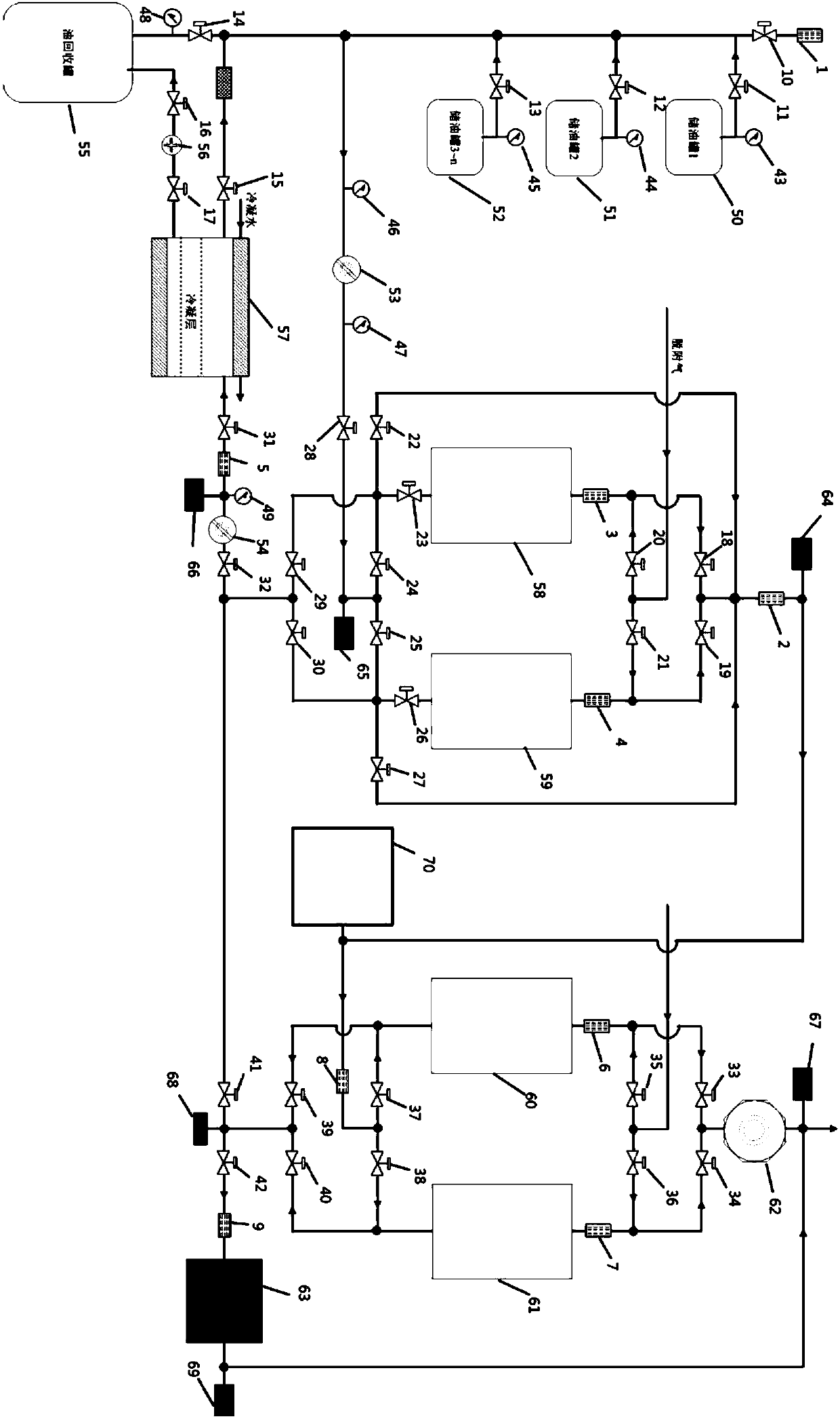
[0012] see figure 1An oil and gas recovery and waste gas treatment system of the present invention includes an oil storage tank, a flame arrester, an on-off valve, a pressure sensor, a first vacuum pump 53, a second vacuum pump 54, a recovery oil tank 55, an oil return pump 56, and a low-temperature circulating water condenser 57. , the first adsorption tank 58, the second adsorption tank 59, the third adsorption tank 60, the fourth adsorption tank 61, the adsorption fan 62, the catalytic incinerator 63, the first band FID gas chromatography 64, the second band FID gas chromatography 65, The third belt FID gas chromatography 66, the fourth belt FID gas chromatography 67, the fifth belt FID gas chromatography 68, the sixth belt FID gas chromatography 69 and the filling area 70, the oil storage tank is respectively connected with the inlet of the recovery oil tank 55 , the second band FID chromatography 65 is connected, the outlet of the said recovery oil tank 55 is connected wi...


PUM


Abstract

The invention provides an oil gas recovery and exhaust gas treatment system which comprises an oil storage tank, a back-fire relief valve, a switching valve, a pressure sensor, a first vacuum pump, asecond vacuum pump, a recovery oil tank, an oil return pump, a low-temperature circulating water condenser, a first adsorption tank, a second adsorption tank, a third adsorption tank, a fourth adsorption tank, an adsorption fan, a catalytic incinerator, first gas chromatography with FID, second gas chromatography with FID, third gas chromatography with FID, fourth gas chromatography with FID, fifth gas chromatography with FID and sixth gas chromatography with FID and a filling region. Concentration of gas in the oil tank is judged by monitoring the pressure online, logic valves are controlled,oil gas in the oil tank is conveyed to condensed recovery gas through a pipeline, most of oil gas is liquefied by way of pressurizing by the vacuum pumps, a small amount of gas which cannot be liquefied enters an activated carbon adsorption system, and is enriched and enters a condensing system to be recovered through vacuum adsorption, so that the optimum treatment effect can be achieved.

Description

【Technical field】 [0001] The invention relates to the technical field of oil and gas recovery, in particular to an oil and gas recovery and waste gas treatment system. 【Background technique】 [0002] Existing oil and gas recovery technologies include common methods such as adsorption, absorption, condensation and membrane separation systems. The adsorption method utilizes the adsorption force of the adsorbents such as activated carbon, silica gel or active fiber to the oil / air mixture to realize the separation of oil / gas and air. It has high treatment efficiency and low emission concentration, which can reach very low values. The absorption method separates oil and gas from air according to the solubility of each component in the mixed oil and gas in the absorbent. The process is simple and the investment cost is low. The direct conversion of phase to liquid phase. The process principle is simple and the economic benefits are the most impressive. Direct combustion method ...

Claims


Application Information

Patent Timeline
IPC IPC(8): B01D53/00B01D53/02B01D53/30F23G7/07
CPCB01D53/002B01D53/02B01D53/30F23G7/07B01D2253/102B01D2257/708
Inventor 王平
Owner 浙江赛鹭鑫仪器有限公司
Why Eureka
Try Eureka