Composite film and preparation method thereof

A composite film, polymer material technology, applied in the direction of ion implantation plating, coating, metal material coating process, etc., can solve the problems of complex lithography technology, high brittleness of composite materials, covering and other problems

Inactive Publication Date: 2018-04-20
ENN SCI & TECH DEV
View PDF6 Cites 16 Cited by
  • Summary
  • Abstract
  • Description
  • Claims
  • Application Information

AI Technical Summary

Problems solved by technology

[0003] However, although most objects have good emissivity in the 8-13 micron waveband, they cannot achieve high reflectivity for the rest of the waveband (such as the visible light band, etc.), and the absorption of these heat covers the effect of radiation cooling. achieve cooling
In order to solve this problem, people have tried the research and development of a variety of composite materials. At present, the research and development are mainly in the following three forms. The first is to cover the surface of the metal material within the wavelength range of 8-13 microns Composite materials formed by materials with high emissivity, such as plating silicon dioxide, calcium fluoride, etc. on highly polished aluminum plates; Composite materials formed by coatings with high emissivity in the remaining wave bands (such as visible light bands, etc.), such as depositing zinc sulfide on the surface of polyethylene terephthalate (PET) plastics, etc.; studies have found that: the two composite materials The refrigeration effect is difficult to meet the actual needs. At the same time, these two composite materials are prepared by surface deposition, which makes the obtained composite materials more brittle, which is not conducive to practical applications; the third is a high emissivity in the atmospheric window. In the rest of the region (such as the visible light region, etc.), photonic crystal materials with high reflectivity, although this material has a good cooling effect, are expensive, and the lithography technology is complicated, so it is not suitable for industrial production and application.

Method used


Image

  • Composite film and preparation method thereof
  • Composite film and preparation method thereof
  • Composite film and preparation method thereof

Examples


preparation example Construction

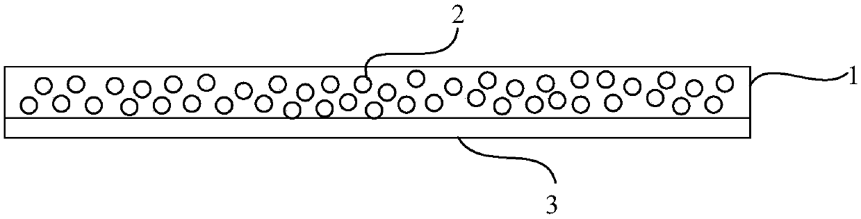
[0052] On the other hand, an embodiment of the present invention provides a method for preparing a composite membrane as described above, including:

[0053] Dispersing the radiator in a solution of a transparent base material, and performing molding treatment to obtain a transparent base film in which the radiator is dispersed;

[0054] The radiator includes a radiator of a first band and a radiator of a second band, the infrared emission peak of the radiator of the first band is located in or covers the range of the first band of the infrared radiation band, and the radiator of the second band The infrared emission peak is located or covered in the second band range of the infrared radiation band, wherein the first band range refers to the band range of 8-10um, and the second band range refers to the band range of 10-13um; and The average emissivity of the first waveband radiator and the second waveband radiator in the infrared radiation waveband are both greater than or equ...

Embodiment 1

[0073] In Example 1, the first waveband radiator is selected from silicon dioxide powder with a particle size of 2 microns, the second waveband radiator is selected from silicon dioxide powder with a particle size of 7 microns, and the transparent base material is selected from TPX.

[0074] 1. Preparation of casting solution:

[0075] Disperse silicon dioxide powder with a particle size of 2 microns and silicon dioxide powder with a particle size of 7 microns in cyclohexane at a volume ratio of 1:2, and ultrasonically 30 min at room temperature to form a uniform dispersion. Stir at 50-70°C for 12 hours and dissolve in the dispersion to form a casting solution. Wherein, the mass percentage of TPX in the casting solution is 15%, the mass percentage of silicon dioxide powder is 6%, the mass percentage of solvent cyclohexane is 79%, the silicon dioxide powder and TPX The volume ratio is 15:100.

[0076] 2. Preparation of a transparent base film dispersed with radiators:

[007...

Embodiment 2

[0081] In Example 2, the first waveband radiator is selected from silica microbeads with a particle size of 3 microns, the second waveband radiator is selected from PVC, and the transparent base material is TPX.

[0082] 1. Surface treatment of inorganic filler silica beads:

[0083] Alcoholyze the silane coupling agent (KH570) under acidic or alkaline conditions for 1 hour, add silica microbeads with a particle size of 3 microns to a mixed solvent of cyclohexane and chloroform, and react at 70°C for 4 hours , and suction-filtered and dried to obtain the surface-treated inorganic filler.

[0084] 2. Preparation of casting solution:

[0085] Disperse the treated silica microbeads in a mixed solvent of cyclohexane and chloroform, ultrasonicate at room temperature for 30 minutes to form a uniform dispersion, and dissolve PVC and TPX in the said Casting fluid is formed in the dispersion. Wherein, the mass percentage of TPX in the casting solution is 15%, the mass percentage of ...


PUM

PropertyMeasurementUnit
thicknessaaaaaaaaaa
thicknessaaaaaaaaaa
particle diameteraaaaaaaaaa

Abstract

The invention relates to the technical field of radiation refrigeration, in particular to a composite film, a preparation method and application thereof. The preparation method of the composite film has the advantages of simple process, wide material selection and low cost. The obtained composite film has good refrigeration effect and good flexibility at the same time, is suitable for a variety ofapplication scenes, and has a wider application range. The composite film provided by the embodiment of the invention includes a transparent matrix membrane and radiators dispersed in the transparentmatrix membrane. The radiators include first waveband radiators and second waveband radiators, wherein the infrared emission peak of the first waveband radiators is located or covered in a waveband range of 8-10microm, the infrared emission peak of the second waveband radiators is located or covered in a waveband range of 10-13microm, and the average emission rates of the first waveband radiatorsand the second waveband radiators in the infrared radiation waveband are both greater than or equal to 90%, and the average absorption rates in the rest wavebands is less than or equal to 10%. The composite film provided by the embodiment of the invention can be used for preparation of refrigeration materials.

Description

technical field [0001] The invention relates to the technical field of radiation refrigeration, in particular to a composite membrane and a preparation method thereof. Background technique [0002] Those bands with high transmittance where electromagnetic waves are less reflected, absorbed and scattered through the atmosphere are called atmospheric windows. For example: 0.3-2.5 microns, 3.2-4.8 microns, and 8-13 microns, etc. Among them, most objects on the surface have good emissivity in the 8-13 microns band, that is, they can dissipate their own heat at 8-13 The form of micron electromagnetic waves is emitted through the atmospheric window to the outer space where the temperature is close to absolute zero, so as to achieve the purpose of self-cooling. This technology does not require external energy input, has no pollution to the environment, and has positive significance for improving the indoor thermal environment of buildings and environmental protection. [0003] Ho...

Claims


Application Information

Patent Timeline
Patent Type & Authority Applications(China)
IPC IPC(8): C08L23/20C08L27/16C08L33/12C08L27/06C08K9/06C08K3/36C08K3/34C08J5/18C23C14/20C23C14/35
CPCC08J5/18C08J2323/20C08J2333/12C08J2427/06C08J2427/16C08K3/34C08K3/36C08K9/06C08K2201/003C08K2201/014C23C14/205C23C14/35
Inventor 刘岩魏彦存孟垂舟杨圆明姜恒马欣欣王汉清韩磊
Owner ENN SCI & TECH DEV
Why Eureka
Try Eureka