Fiber bragg grating temperature/strain sensing system and demodulation method thereof

A fiber grating and strain sensing technology, which is applied in the direction of transmitting sensing components, thermometers, and converting sensor output with optical devices, can solve the problems of reducing strain accuracy in low frequency bands, fiber laser noise, and affecting the accuracy of fiber laser sensors. The effect of solving the deterioration of strain accuracy and low power requirements

Active Publication Date: 2018-06-05
宁波联河光子技术有限公司
View PDF7 Cites 19 Cited by
  • Summary
  • Abstract
  • Description
  • Claims
  • Application Information

AI Technical Summary

Problems solved by technology

Although this scheme has the characteristics of low cost and easy multiplexing, it is difficult to improve the sensitivity performance due to the wide reflection bandwidth of FBG
The second is the PDH demodulation technology that has emerged in recent years, using a single-frequency laser to lock on the edge of the reflection peak of FBG, the resonance peak of PSFBG (π-phase-shifted FBG) or FFPI (fiber FP cavity), and the strain resolution can even reach However, there are some shortcomings in the PDH demodulation scheme: a. The strain accuracy of this scheme is directly affected by the frequency stability of the single-frequency laser, which puts forward high requirements for the

Method used


Image

  • Fiber bragg grating temperature/strain sensing system and demodulation method thereof
  • Fiber bragg grating temperature/strain sensing system and demodulation method thereof
  • Fiber bragg grating temperature/strain sensing system and demodulation method thereof

Examples


Embodiment Construction

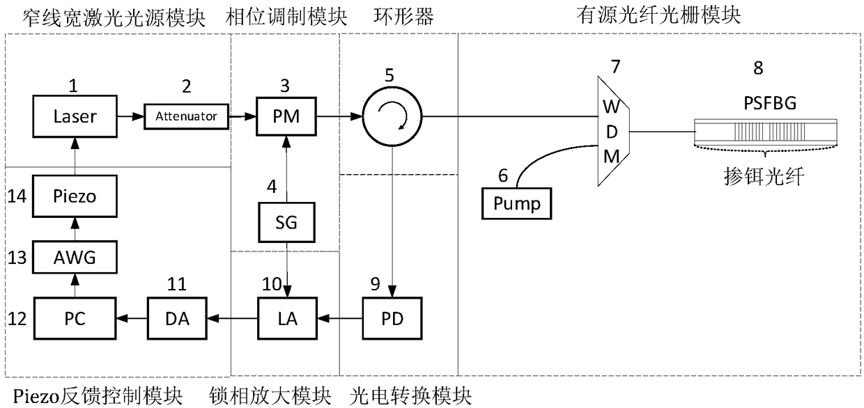
[0043] Such as figure 1 As shown, this embodiment includes: a narrow linewidth laser source module, a phase modulator module, a circulator 5, an active fiber grating module, a photoelectric conversion module, a lock-in amplifier and a feedback control module, wherein: the narrow linewidth laser source module Generate a single-frequency seed laser with a certain optical power, and the phase modulator module phase-modulates the seed light to generate carrier and sidebands, and enter the active fiber grating module from ports 1 and 2 of the circulator; the seed laser that enters the active fiber grating The frequency and phase of the laser output from the active fiber grating will be controlled, and the laser output from the active fiber grating will enter the photoelectric conversion module through the 2 and 3 ports of the circulator to realize the conversion of the optical signal and the electrical signal to obtain the beat frequency signal; the lock-in amplifier from Extract ...


PUM


Abstract

The invention relates to a fiber bragg grating temperature/strain sensing system and a demodulation method thereof. The method comprises the following steps: after seed layer generated by a narrow linewidth laser light source module generates a sideband through a phase modulation module, injecting into active fiber grating stimulated by pump light through a circulator and a wavelength division multiplexer in an active fiber grating module; and performing photovoltaic conversion on return light and a photoelectric detector connected with the circulator to acquire a beat frequency signal, extracting a component, namely an error signal reflecting the center frequency deviation between the narrow linewidth laser and the active fiber grating, at the phase modulation frequency position by a phase-locked amplifier, and generating a feedback voltage signal by a feedback control module by virtue of the error signal to control the center frequency of the narrow linewidth laser so as to realize injection locking between the narrow linewidth laser and the active fiber grating. The quasi-static accuracy of p-epsilon can be achieved; the characteristic of adjustable strain sensitivity is achieved; and the problems of mode jump, relaxation shock and low-frequency phase noise in a fiber laser sensor can be effectively solved.

Description

technical field [0001] The invention relates to a technology in the field of optical fiber sensing, in particular to a high-resolution optical fiber grating temperature / strain sensing system and a demodulation method thereof. Background technique [0002] Strain sensing technology is widely used in engineering fields, such as underwater sound field monitoring, structural health monitoring, oil pipeline safety monitoring, seismic wave monitoring, etc. Traditional strain sensors are generally mechanical or electromagnetic, and there are many problems. For example, in a strong electric field environment, traditional strain sensors are susceptible to electromagnetic interference and cannot work normally; in flammable and explosive environments, electric sparks will be generated. Cause accidents; in underwater or underground environments, electrical components will corrode; in applications that require arraying, traditional strain sensors are difficult to connect into large-scale...

Claims


Application Information

Patent Timeline
IPC IPC(8): G01K11/32G01B11/16G01D5/353G01K11/3206
CPCG01B11/16G01D5/3538G01K11/32
Inventor 刘庆文何祖源赵双祥
Owner 宁波联河光子技术有限公司
Why Eureka
Try Eureka