Sinter cooler with radiation heat recoverer and cooling method

A cooler and recycler technology, applied in the field of ironmaking, can solve the problems of low utilization rate of waste heat, large air leakage rate of the cooler, material wear at the feed port, etc., and achieves high waste heat recovery efficiency, small equipment maintenance, and sealing reliable results

Active Publication Date: 2018-07-10
ZHONGYE-CHANGTIAN INT ENG CO LTD
View PDF4 Cites 2 Cited by
  • Summary
  • Abstract
  • Description
  • Claims
  • Application Information

AI Technical Summary

Problems solved by technology

No matter which way you choose, it will cause a high investment cost, which is not cost-effective in terms of economic indicators;
[0007] 2) The open circulation of the air flow leads to low utilization rate of waste heat and pollutes the environment: Since the air flow of the "extraction type longitudinal plate cooling technology" is an open circuit circulation, the air from the waste heat boiler is directly exhausted and not recycled, resulting in more than 100 Sensible heat of the air at a high temperature is wasted, and the discharged air contains a large amount of small particles of dust, causing a certain degree of particulate matter pollution to the atmosphere;
[0008] 3) The material at the feed inlet is severely worn: due to the "ventilated longitudinal plate cooling technology" that sets the material seal at the feed chute, there will be a friction distance between the lower part of the material seal and the upper layer of the material surface in the plate cooler box
At this time, the sintered material is easily pulverized and broken when it is rubbed under the double-layer harsh working conditions of high temperature and upper material column extrusion, thereby reducing the yield of the sintering machine;
[0009] 4) The environmental pollution is serious: due to the negative pressure ventilation technology adopted in the "ventilation type longitudinal plate cooling technology", it does not set a sealing cover device at the lower tray of the box body
In this way, when the sinter is scraped off by the scraper device, it is easy to cause a large number of fine particles and dust to splash
And once the exhaust fan breaks down, all the material dust pushed around the plate cooler will enter the atmosphere, causing extremely bad impact on the operating environment beside the machine;
[0010] 5) The thermal efficiency of the waste heat boiler has not reached the highest: because the "ventilated longitudinal plate cooling technology" does not accurately classify the air passing through the material layer according to the air temperature, but mixes it all into the waste heat boiler, so when the outlet air temperature of the low temperature section is too low , it will inevitably lower the temperature of the air entering the waste heat boiler, thereby reducing the thermal efficiency value of the waste heat boiler
No matter which cooling method is used, the cooling machine has problems such as large air leakage rate, high fan power consumption, low sensible heat recovery rate, and low boiler thermal efficiency.
In other words, in the current environment where the market has increasingly stringent requirements for energy saving and green manufacturing in sinter production, the original equipment structure has been difficult to achieve efficient recovery and utilization of sinter sensible heat

Method used


Image

  • Sinter cooler with radiation heat recoverer and cooling method
  • Sinter cooler with radiation heat recoverer and cooling method
  • Sinter cooler with radiation heat recoverer and cooling method

Examples


Embodiment 1

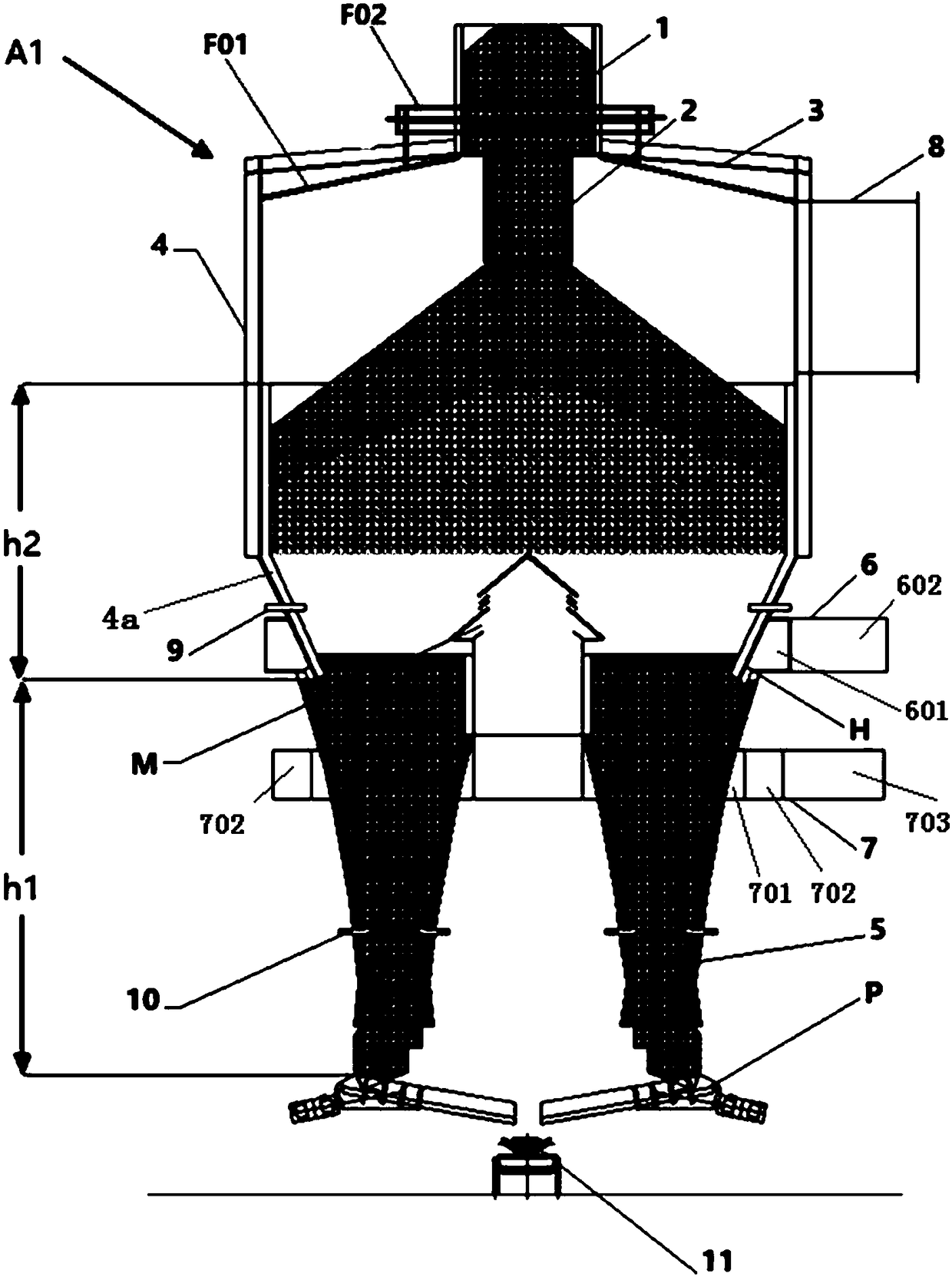
[0120] The height of the tower body consisting of the top cover and the tower wall is 9 meters, and the outer diameter of the tower body is 13 meters. The height of the discharge cone is 7 meters. Under the top cover and close to the top cover, a ring-shaped second radiant heat recovery device F01 is formed by assembling a plurality of ring-shaped hollow plates.

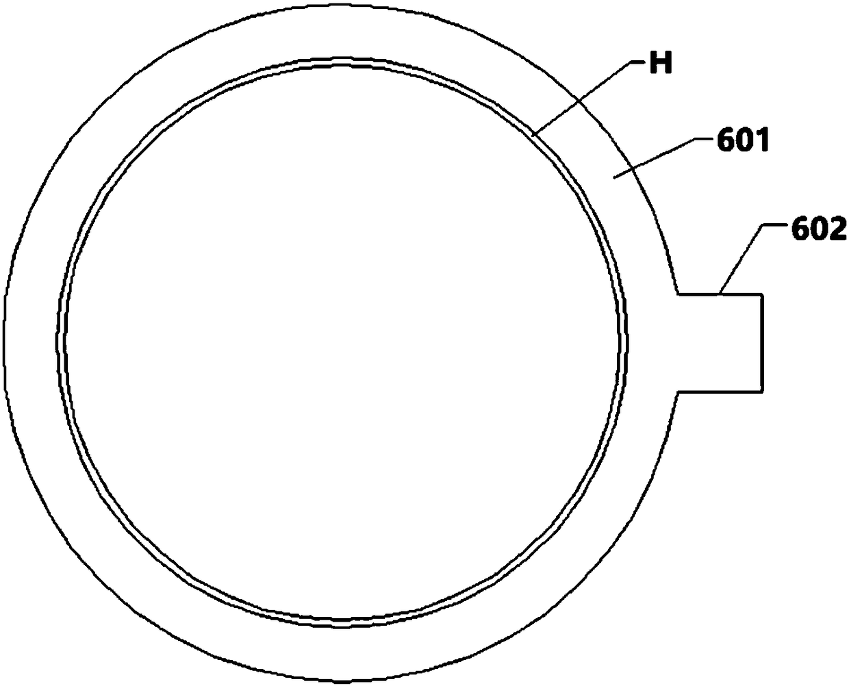
[0121] The diameter of the hood is 2.5 meters. The inner diameter of the wind ring is about 11 meters.

[0122] The daily processing capacity of sinter is 8600 tons / day. The temperature of the sintered ore before entering the silo is about 700°C, and the temperature of the hot air at the hot air outlet 8 reaches about 498°C. The recovered heat is used to generate electricity, and the power generation is about 36 kWh.

[0123] Compared with the prior art annular cooler, the advantages are: high power generation, low air leakage rate, small dust emission, simple and reliable equipment, and better sealing performanc...

Embodiment 2

[0126] The device is the same as in Example 1, except that the second radiant heat recoverer F01a is further arranged at the front end of the hot air outlet 8; a tube-and-tube heat exchanger is adopted, such as Figure 13 shown.


PUM


Abstract

The invention disclose a vertical type cooler. The cooler comprises a material bin (1), a material distribution pipe (2), a tower body composed of a tower body top cover (3) and a tower wall (4), a plurality of discharging cone hoppers (5) located below the tower wall (4), a wind ring (H), a wind cap (M), a radiation heat recoverer (F01) located under the tower body top cover (3) and is close to the tower body top cover (3) and a hot wind outlet (8) arranged above tower wall (4) or on the tower body top cover (3), wherein the top cover (3) is fixedly connected with the upper end of the tower wall (4), the material bin (1) is arranged above the top cover (3), the upper end of the material distribution pipe (2) is connected with the bottom of the material bin (1), and the lower end of the material distribution pipe (2) extends into the positon below the top cover (3); and the plurality of discharging cone hoppers (5) are annularly distributed below the tower wall (4) or are uniformly distributed in the circumferential direction, a circle of fixed clearance is formed between the lower part of tower wall (4) and the tops of the plurality of discharging cone hoppers (5) and serves as the wind ring (H), the wind cap (M) extending upwards into the inner space of the tower body is arranged at the center of the bottom of the tower body, and discharging equipment (P) is arranged below each of the discharging cone hoppers (5).

Description

technical field [0001] The invention relates to a vertical sinter cooler and a sinter cooling method, belonging to the fields of ironmaking and environmental protection. Background technique [0002] In the modern sintering process, "cooling" is one of the most critical processes. After the sintered ore has been roasted by the sintering machine, it has formed a high-temperature finished ore. How can it be protectively cooled without affecting its quality and yield, so that it can be sent to the finished product ore bin through a belt conveyor, and at the same time The perfect recovery and utilization of the sensible heat energy it carries has always been a problem that technicians in the industry have been constantly studying. Since the 1960s, the cooling process of sinter has been developed rapidly, which is mainly divided into three categories: belt cooling, ring cooling and disk cooling. In the late market competition, the strip cooling technology was eliminated, and th...

Claims


Application Information

Patent Timeline
Patent Type & Authority Applications(China)
IPC IPC(8): F27D15/02F27D17/00
CPCF27D15/0286F27D17/004F27D2017/006F27M2003/04
Inventor 叶恒棣张震贺新华
Owner ZHONGYE-CHANGTIAN INT ENG CO LTD
Why Eureka
Try Eureka