

Cerium-based catalyst based method for reducing emission and denitrifying and removing dioxin of sintering smoke
A cerium-based catalyst, sintering flue gas technology, applied in chemical instruments and methods, physical/chemical process catalysts, metal/metal oxide/metal hydroxide catalysts, etc., can solve the problem of limited dioxin emission reduction effect, operation Complex, high price and other problems, to achieve the effect of low-temperature catalytic degradation, improve removal efficiency, and reduce emissions
- Summary
- Abstract
- Description
- Claims
- Application Information
AI Technical Summary
Problems solved by technology
Method used
Image

Examples
Embodiment 1
[0050] In this embodiment, a method based on a cerium-based catalyst for emission reduction and sintering flue gas denitrification and dioxin removal, the flue gas passes through an emission reduction device loaded with a cerium-based catalyst, and NH is blown into the emission reduction device 3 and air, wherein the cerium-based catalyst includes Ce:Mn and Fe, wherein the molar ratio of Ce:Mn is 0.25-1, and Fe is an auxiliary agent, and the addition ratio ranges from Fe:Mn molar ratio of 0.25-0.5. The cerium-based catalyst in this embodiment includes Ce:Mn and Fe, wherein the molar ratio of Ce:Mn is both 0.25, Fe is an auxiliary agent, and the range of Fe:Mn molar ratio is 0.25.
[0051] where NH 3 The injection quality is 10-20% of the mass content of nitrogen oxides in the sintering flue gas, which is 10% in this embodiment; the injection amount of air is 5-10% of the other contents of the sintering flue gas, which is 8% in this embodiment. No additional heating of the sin...
Embodiment 2
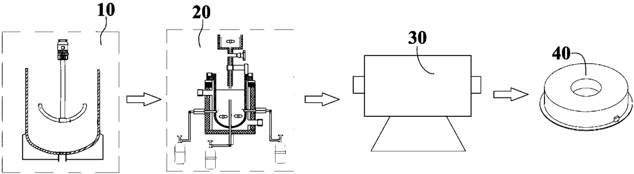
[0066] Refer to attached figure 1 As shown, a production system of a cerium-based catalyst for synergistically removing dioxins and nitrogen oxides of the present invention includes a mixing device 10, a preparation device 20 and a roasting device 30 arranged in sequence; wherein the mixing device 10 is used for The reaction component solutions are mixed, and the mixing device 10 includes a mixing tank 300 and a stirring mechanism 310, the stirring mechanism 310 is arranged on the top of the mixing tank 300, and the stirring blade 311 at the bottom of the mixing mechanism 310 extends to the inside of the mixing tank 300 , the bottom of the mixing tank 300 is connected to the preparation device 20 through a pipeline, and a control valve 301 is arranged on the pipeline.
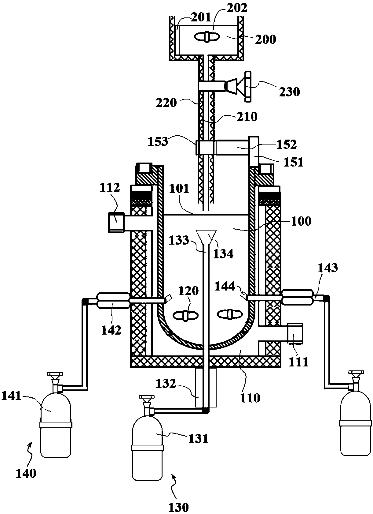
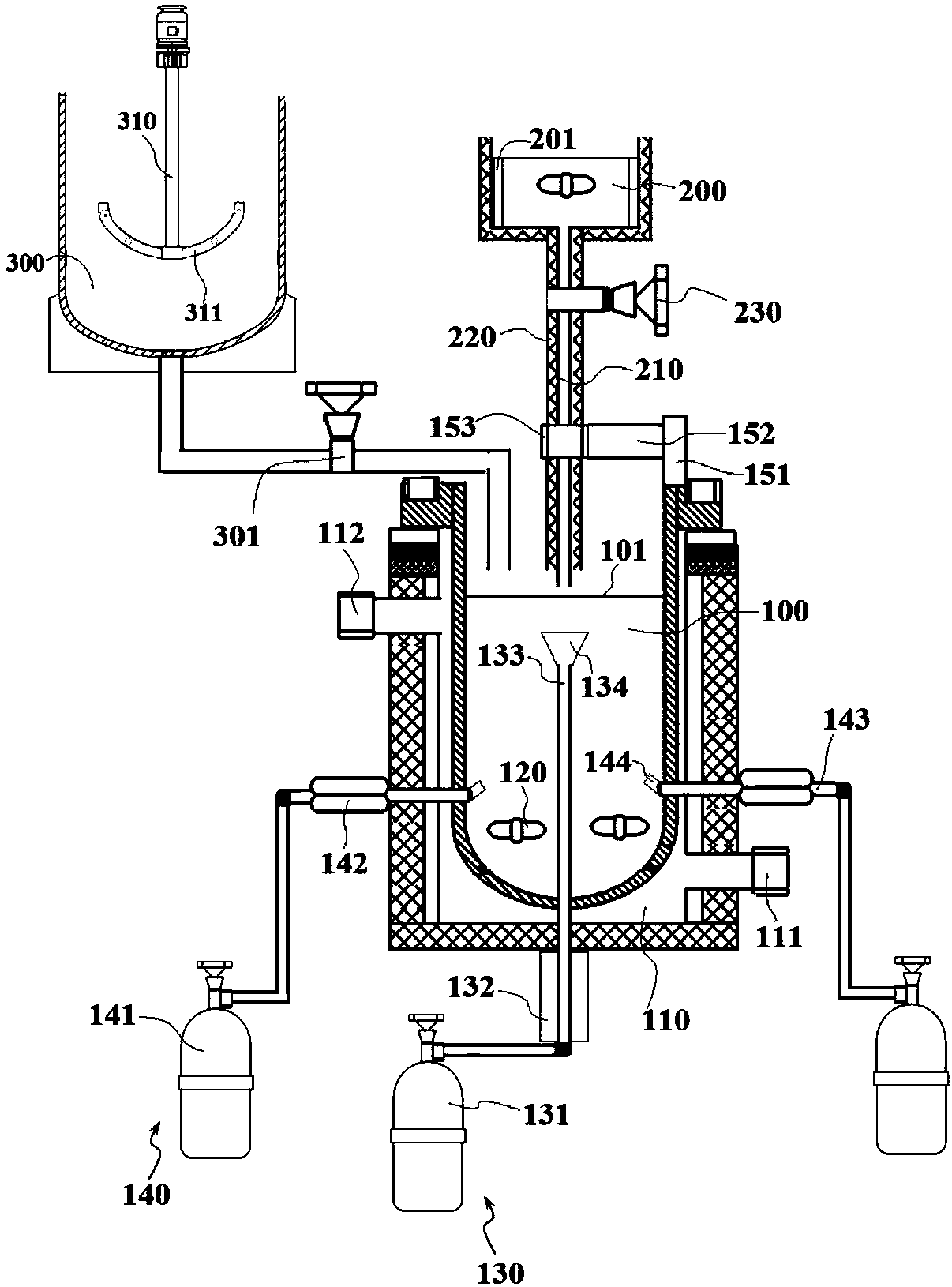
[0067] Such as figure 2 and image 3 As shown, the above-mentioned preparation device 20 is used to prepare catalyst products. The preparation device 20 includes a reaction chamber 100 and an oxalic acid poo...
Embodiment 3
[0075] The basic content of this embodiment is the same as that of Example 1, except that in step 400, during the preparation of the catalyst, additives are added to the calcined product, and then the mixture of the calcined product and the additive is added to the grinding device 40 for grinding , wherein the additives include potassium permanganate or potassium manganate, potassium permanganate or potassium manganate can decompose oxygen and manganese oxide under heating conditions, oxygen is beneficial to the catalytic effect, and manganese oxide is beneficial to supplement the consumption of catalyst manganese.
PUM
| Property | Measurement | Unit |
|---|---|---|
| Aperture | aaaaa | aaaaa |
Abstract
Description
Claims
Application Information