Oxygen direct-injection pure-hydrogen combustion engine and power system thereof

A combustion engine and engine technology, applied in the direction of combustion engine, internal combustion piston engine, gaseous engine fuel, etc., can solve the problems of being unable to promote, expensive, and consuming other resources

Active Publication Date: 2018-08-24
SHANGHAI KELAIPU ENERGY TECH CO LTD
View PDF5 Cites 15 Cited by
  • Summary
  • Abstract
  • Description
  • Claims
  • Application Information

AI Technical Summary

Problems solved by technology

The promotion of hydrogen energy power needs to solve three technical problems: one is to produce a large amount of cheap hydrogen, the traditional electrolysis method is expensive and consumes other resources, so it cannot be promoted; the second is the safe storage and transportation of hydrogen; the third is the high High-performance, inexpensive hydrogen supply system

Method used


Image

  • Oxygen direct-injection pure-hydrogen combustion engine and power system thereof
  • Oxygen direct-injection pure-hydrogen combustion engine and power system thereof
  • Oxygen direct-injection pure-hydrogen combustion engine and power system thereof

Examples


Embodiment 1

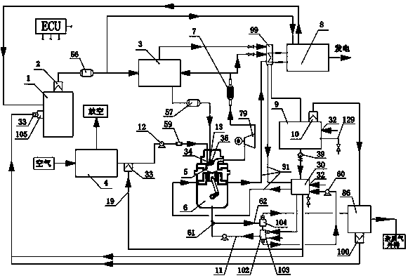
[0061] Oxygen direct injection pure hydrogen combustion internal combustion engine power system of the present invention such as figure 1 As shown, it includes ECU, hydrogen fuel engine, magnesium hydride storage tank 1, booster bed 3, pressure swing adsorption oxygen generator 4, condenser 99, exhaust gas expander 79, three-way catalytic converter 7, Clapp unit, hydrogen purification Unit 86, cooling water tank 30, booster pump 12, return water pump 60, gas-liquid separator 9, low-pressure hydrogen buffer tank 56, high-pressure hydrogen buffer tank 57, circulating water tank 102, No. 2 gas-liquid separator 104 and high-pressure oxygen buffer tank 59. Such as Figure 9 As shown, the hydrogen fuel engine is a two-stroke engine, including a cylinder 5 , a cylinder head 40 , a crankcase 35 and a water pan 6 . A spark plug 36, a hydrogen nozzle 13 and an oxygen nozzle 34 are arranged on the cylinder head, and an exhaust hole 41 is arranged on the cylinder wall. A crankshaft 45 ...

Embodiment 2

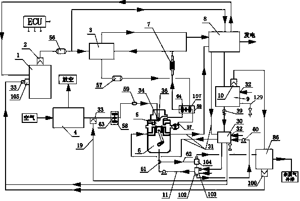
[0096] Another embodiment of the present invention is as figure 2 As shown, it includes ECU, hydrogen fuel engine, magnesium hydride storage tank 1, booster bed 3, pressure swing adsorption oxygen generator 4, three-way catalytic converter 7, composite Clapp unit, low-pressure hydrogen buffer tank 56, high-pressure hydrogen buffer tank 57. High-pressure oxygen buffer tank 59, hydrogen purification unit 86, gas-liquid separator 9, circulating water tank 102, No. 2 gas-liquid separator 104, cooling water tank 30 and turbocharger unit 58. The hydrogen outlet of the magnesium hydride storage tank is provided with a hydrogen filter membrane 2 , the gas outlet of the gas-liquid separator is provided with a gas filter membrane 10 , and the cooling water tank 30 and the gas-liquid separator 9 are provided with a drain port 129 . The circulating water tank 102 is provided with a lubricant adding port 103 and a drain port, the drain port is provided with a lubricant filter film, and th...

Embodiment 3

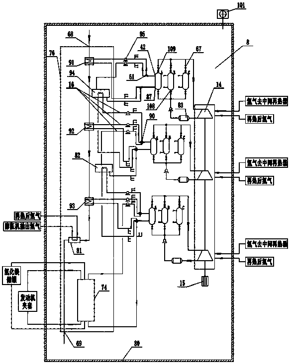
[0127] The third embodiment of the present invention is as Figure 8 As shown, it includes a hydrogen fuel engine, a magnesium hydride storage tank 1, a pressure swing adsorption oxygen generator 4, a three-way catalytic converter 7, a booster pump 12, an exhaust waste heat utilization unit, a gas-liquid separator 9, a cooling water tank 30, and a hydrogen purification unit 86 , circulating water tank 102 , No. 2 gas-liquid separator 104 , turbocharger unit 58 , low-pressure hydrogen buffer tank 56 and high-pressure oxygen buffer tank 59 . The hydrogen outlet of the magnesium hydride storage tank is provided with a hydrogen filter membrane 2 , the gas outlet of the gas-liquid separator is provided with a gas filter membrane 10 , and the cooling water tank 30 and the gas-liquid separator 9 are provided with a drain port 129 . The circulating water tank 102 is provided with a lubricant adding port 103 and a drain port, the drain port is provided with a lubricant filter film, and t...


PUM


Abstract

The invention relates to an oxygen direct-injection pure-hydrogen combustion engine and a power system thereof. The oxygen direct-injection pure-hydrogen combustion engine comprises a hydrogen fuel engine body, a magnesium hydride storage tank, a pressure swing adsorption oxygenerator, a three-way catalyst, a tail gas waste heat utilization unit and a hydrogen purification unit. The magnesium hydride storage tank is connected to a hydrogen opening of the hydrogen fuel engine body through a low-pressure hydrogen buffering tank, and the pressure swing adsorption oxygenerator is connected to an oxygen nozzle of the hydrogen fuel engine body through a high-pressure oxygen buffering tank. Exhausting holes of the hydrogen fuel engine body are connected to the three-way catalyst through a tail gas expander or a turbocharging unit, and an outlet of the three-way catalyst is connected to a gas-liquid separator through a kelaipu unit / combined type kelaipu unit. A gas outlet of the gas-liquid separator is connected to a steam inlet of the magnesium hydride storage tank through the hydrogen purification unit, and a water outlet of the gas-liquid separator is connected to a cooling water tank.The oxygen direct-injection pure-hydrogen combustion engine is combined with the kelaipu unit / combined type kelaipu unit through the hydrogen fuel engine body, tail gas waste heat of the engine body is fully utilized, and the heat efficiency of the engine body is improved.

Description

technical field [0001] The invention belongs to the technical field of new energy engines, and relates to an energy-saving and environment-friendly oxygen direct injection pure hydrogen combustion internal combustion engine power system. Background technique [0002] Energy shortage, environmental pollution, and global climate change make it urgent to develop clean, efficient, safe and sustainable energy, among which hydrogen energy is being valued by more and more countries. In the 21st century, the engine industry has developed rapidly, but gasoline engines and diesel engines are still the main types of vehicle engines. Both gasoline and diesel are non-renewable resources. In order to alleviate a series of negative effects brought about by the scarcity of petroleum resources and reduce air pollution and engine exhaust emissions, it is necessary to find alternative fuels for engines, and hydrogen energy is currently the most ideal clean fuel. With the increasingly stringen...

Claims


Application Information

Patent Timeline
Patent Type & Authority Applications(China)
IPC IPC(8): F02B43/10F02B75/02F02M21/02F01N5/02F01K25/08F02B41/10F02B75/00C01B3/00C01B13/02C25B1/04C25B9/00
CPCC01B3/0031C01B13/0248C01B2210/0009C25B1/04C25B9/00F01K25/08F01N5/02F02B41/10F02B43/10F02B75/002F02B75/02F02B2075/025F02B2075/027F02M21/0206F02M21/0227F02M21/0254F02M21/0263Y02E60/32Y02E60/36Y02T10/12Y02T10/30Y02P20/10Y02P20/129
Inventor 贾鹏
Owner SHANGHAI KELAIPU ENERGY TECH CO LTD
Why Eureka
Try Eureka