
Integrated formation device and method of metal-based carbon nano-composite material parts

A composite material and carbon nanotechnology, which is applied in the direction of additive processing, process efficiency improvement, additive manufacturing, etc., can solve the problem of inability to accurately obtain carbon source gas and hydrogen content, inability to achieve precise control of carbon nanomaterial content, inability to achieve Problems such as real-time monitoring and emission of impurity gases, to achieve the effect of shortening the preparation cycle, realizing real-time monitoring and emission, and realizing the content of enhanced phase

Inactive Publication Date: 2018-08-31
CHONGQING INST OF GREEN & INTELLIGENT TECH CHINESE ACADEMY OF SCI
View PDF4 Cites 7 Cited by
  • Summary
  • Abstract
  • Description
  • Claims
  • Application Information

AI Technical Summary

Problems solved by technology

Since the metal powder is melted after the working head, the working head is controlled by the mechanical system, and the running speed and accuracy are inevitably affected, which will seriously affect the scanning speed and accuracy of the laser beam, and finally affect the mechanical properties of the composite material forming parts
Moreover, in the metal-based carbon nanocomposite material forming device disclosed in the above-mentioned patent, there are no sensors for the content of carbon source gas and reaction gas (hydrogen gas), and the content of carbon source gas and hydrogen gas cannot be accurately obtained. Therefore, it cannot be used as a reinforcing phase. The precise control of the content of carbon nanomaterials cannot realize the real-time monitoring and discharge of impurity gases in the forming device

Method used


Image

  • Integrated formation device and method of metal-based carbon nano-composite material parts
  • Integrated formation device and method of metal-based carbon nano-composite material parts

Examples


Embodiment 1

[0031] Embodiment 1. Integrated forming device for metal-based carbon nanocomposite parts

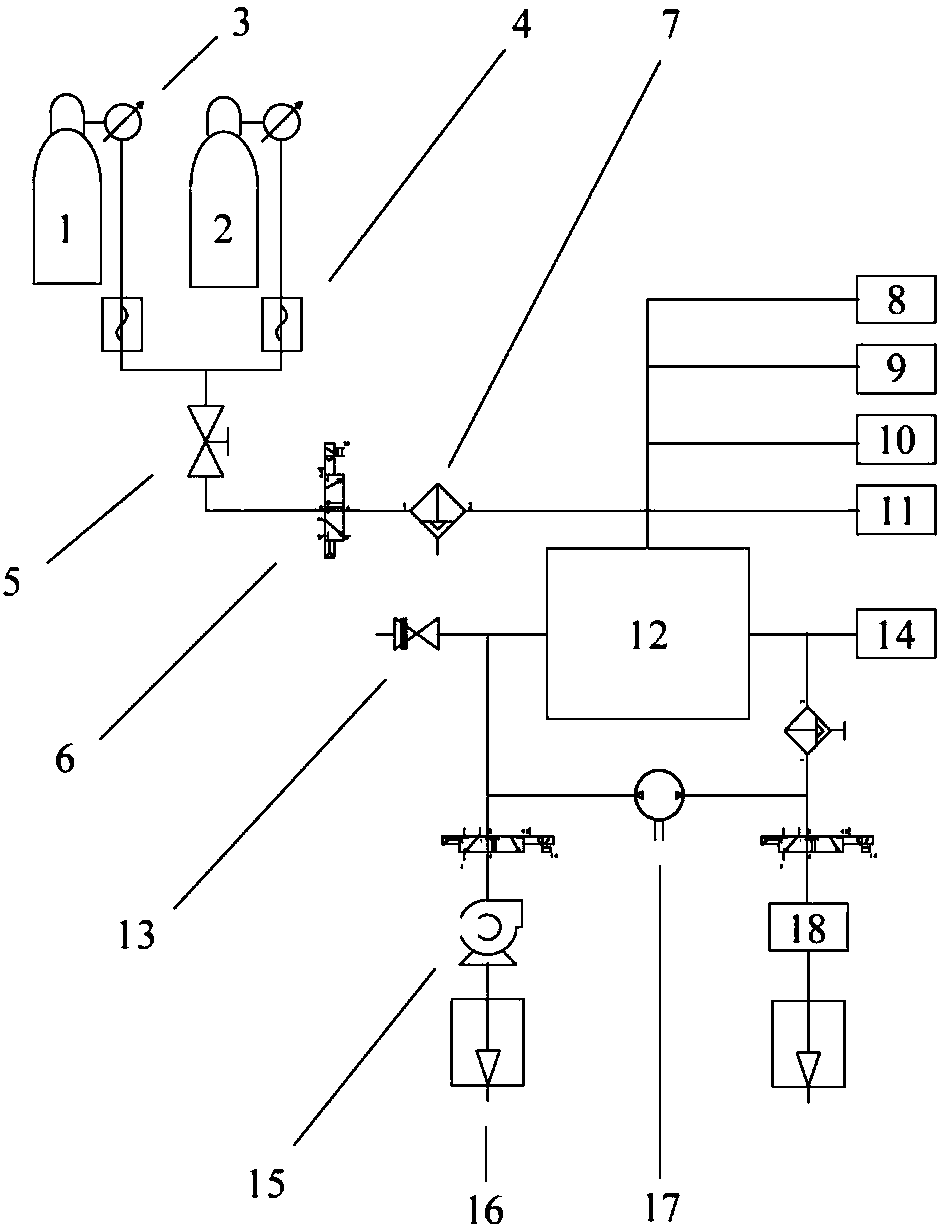
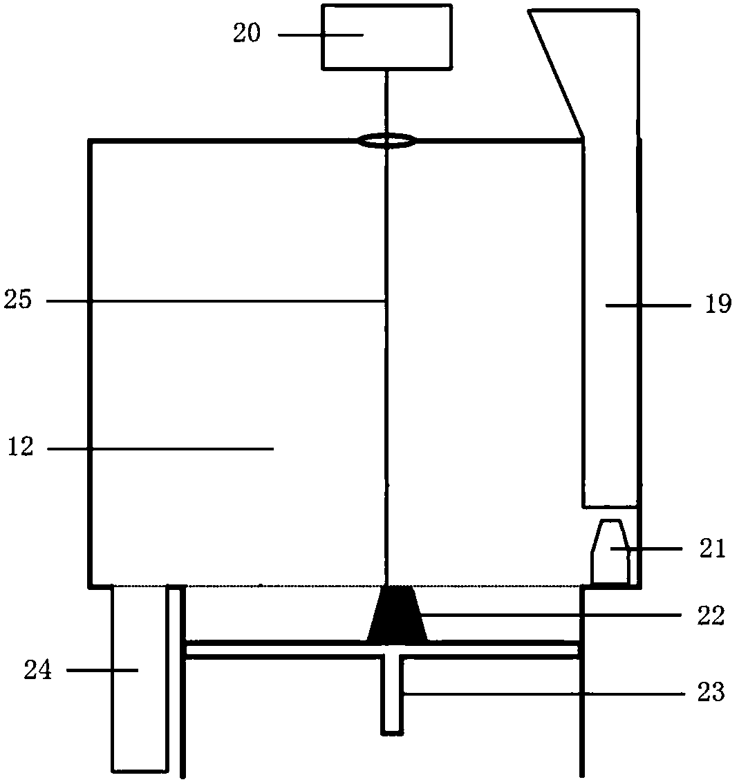
[0032] An integrated forming device for metal matrix carbon nanocomposite parts, its structure is as follows figure 1 As shown, it specifically includes a control system, a forming chamber 12, a vacuum system 15, a carbon source gas supply chamber 1, and a protective gas chamber 2; a carbon source gas detection device 14, a gas circulation system 17, an optical system 20, and a powder feeding system 19 ( like figure 2 shown), exhaust gas treatment system 18, wherein the optical system includes a laser, a laser transmission device, and is equipped with an optical path transmission element, a scanning galvanometer, a focusing lens, a light-transmitting mirror, a protective mirror, etc., and the laser parameters can be adjusted to make the carbon source gas flow in the laser Crack and catalyze various carbon nanomaterials under the action of the beam 25, and compound with the metal matri...

Embodiment 2

[0035] Embodiment 2, integrated forming method of metal-based carbon nanocomposite parts

[0036] An integrated forming method for metal-based carbon nanocomposite parts, comprising the following steps:

[0037] (1) Establish the three-dimensional graphics file of the parts, and carry out hierarchical discretization, generate scanning path data, and import it into the control system;

[0038] (2) First evacuate the forming cavity, and when the oxygen content is less than 0.1vol.%, pass in the protective gas, then supply the carbon source gas and stabilize its concentration at 0-100vol.%, and recycle the protective gas and gas through the gas circulation system carbon source gas;

[0039] (3) The powder feeding system controls the scraper to evenly spread a layer of spherical metal powder on the substrate;

[0040] (4) The laser beam realizes the selective melting of the metal powder according to the three-dimensional graphics file, forms a focused spot on the processing plan...

Embodiment 3

[0044] Embodiment 3. Integrated forming method for functionally graded components of metal-based carbon nanocomposites

[0045] An integrated forming method for functionally graded components of metal-based carbon nanocomposites, comprising the following steps:

[0046] (1) Establish the three-dimensional graphics file of the parts, and carry out hierarchical discretization, generate scanning path data, and import it into the control system;

[0047] (2) Vacuum the forming cavity first, and pass in the protective gas when the oxygen content is lower than a certain concentration value (usually <0.1vol.%), and then control the gas flow meter to continuously supply the carbon source gas according to a certain gas flow value, In order to realize the continuous change of the carbon source gas concentration from 0 to 100vol.%, the protection gas and carbon source gas are recycled through the gas circulation system;

[0048] (3) The powder feeding system controls the scraper to even...


PUM


Abstract

The invention relates to an integrated formation device and method of metal-based carbon nano-composite material parts. The integrated formation device comprises a control system, a formation cavity,a vacuum system, a carbon source gas supply and detection system, a gas circulation system, a laser and an optical system, a powder feeding and paving system and a tail gas treatment system. Accordingto the device disclosed by the invention, metal powder is uniformly paved on a base plate by adopting a scraper, then laser beams are focused on the metal powder, a gaseous carbon source is controlled to be split under an effect of the laser beams and carbon nano-materials are deposited on the surface of a matrix, and the metal-based carbon nano-composite material parts are directly formed in a layer-by-layer working way through selective laser melting formation technology. By adopting the device, concentration values of the carbon source gas and the hydrogen can be accurately acquired, the content of the carbon nano-materials can be quantitatively controlled, and real-time monitoring and emission of impure gas in the formation device also can be realized. Carbon-nano reinforced phases generated in a way of gaseous carbon source diffusion-splitting-deposition are uniformly dispersed and are difficultly aggregated, so that the mechanical performance of the composite material can be effectively enhanced.

Description

technical field [0001] The invention belongs to the technical field of laser preparation of metal-based carbon nanocomposite parts, in particular to a method for in-situ reaction synthesis of metal-based carbon nanocomposites in combination with a selective laser melting method (SLM) and a laser chemical vapor deposition method (LCVD). Devices and methods. Background technique [0002] Metal matrix carbon nanocomposites have excellent physical and mechanical properties. However, the application of metal matrix composites in specific cases requires processing them into parts with specific shapes, which are usually manufactured according to molds or processed later, especially for parts with very complex internal shapes. Traditional methods are time-consuming and labor-intensive. The invention combines SLM and LCVD technology, adds gaseous carbon source in the SLM melting and forming process of metal powder, controls the cracking of gaseous carbon source under the action of ...

Claims


Application Information

Patent Timeline
Patent Type & Authority Applications(China)
IPC IPC(8): B22F3/105B33Y10/00B33Y30/00
CPCB33Y10/00B33Y30/00B22F2999/00B22F10/00B22F12/44B22F12/90B22F10/28B22F12/67B22F12/70B22F10/32B22F10/77B22F3/1007B22F2201/30Y02P10/25
Inventor 段宣明魏文猴范树迁张祺曹洪忠吴文杰王森
Owner CHONGQING INST OF GREEN & INTELLIGENT TECH CHINESE ACADEMY OF SCI
Learn More