Self-suction oil-water separating device

An oil-water separation device, self-priming technology, applied in the direction of liquid separation, separation method, semi-permeable membrane separation, etc., can solve the problems of low separation rate, unfriendly environment, high operating cost, etc., to achieve improved separation rate and low operating cost , good repeatability

Inactive Publication Date: 2018-09-11
湖南国昶能源科技有限公司
View PDF3 Cites 3 Cited by
  • Summary
  • Abstract
  • Description
  • Claims
  • Application Information

AI Technical Summary

Problems solved by technology

[0004] In order to overcome the shortcomings of the existing oil-water separation system technology, the purpose of the present invention is to provide a high-efficiency,

Method used


Image

  • Self-suction oil-water separating device
  • Self-suction oil-water separating device
  • Self-suction oil-water separating device

Examples


Embodiment 1

[0037] In this embodiment, the specific construction steps of the self-priming oil-water separation device are as follows:

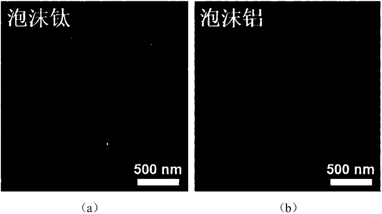
[0038] (1) Carry out anodic oxidation under voltage 40V with diameter 20mm, thick 3mm, the foamed titanium of filter precision 30 μ m, anodic oxidation time is 3h, and electrolytic solution is the mixed solution of the ethylene glycol that contains 0.2wt% ammonium fluoride and water ( The mass fraction of water is 20%), then dried and annealed at 450° C. for 3 h.

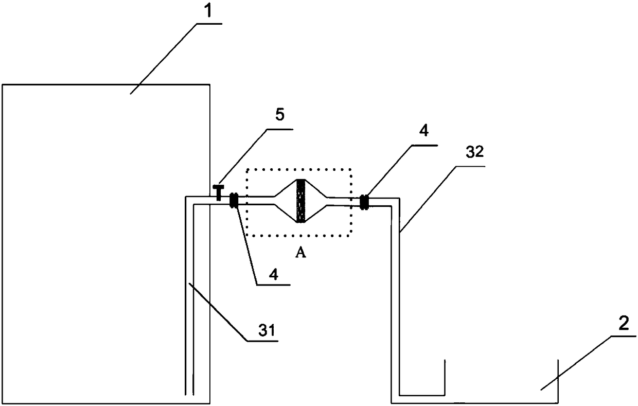
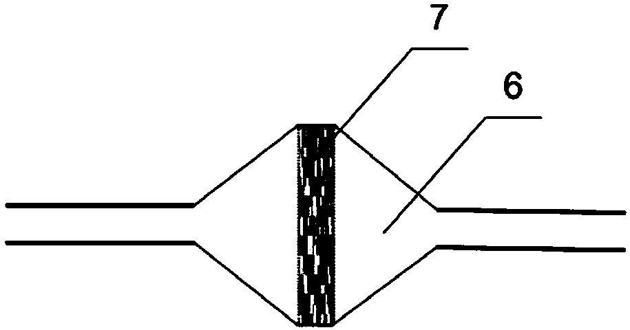
[0039](2) Embed the anodized titanium foam into the bottom of the quartz conical funnel, seal and fix it with silicone glue, apply silicone glue on the connection, buckle another identical conical funnel, and Wait for the glue to solidify to form a spindle-shaped filter chamber with a separation membrane embedded in it.

[0040] (3) An inverted L-shaped quartz tube with an outer diameter of 7 mm and an inner diameter of 3 mm is introduced into the side wall opening of a quartz liquid storage ...

Embodiment 2

[0049] The difference from Example 1 is:

[0050] 1. The metal foam used in step (1) is aluminum foam, the electrolytic solution for anodic oxidation is 2.7wt% oxalic acid solution, and the anodic oxidation time is 15 minutes. Anodized aluminum foam surface microstructure see figure 2 (b).

[0051] 2. Use the same steps as in Example 1 to build an oil-water separation device.

[0052] Through the self-priming oil-water separation device, the separation efficiency of the oil-in-water emulsion of n-hexane can reach more than 99.5%.

Embodiment 3

[0054] The difference from Example 1 is:

[0055] 1. The titanium foam filtration precision parameter used in step (1) is 10 μm.

[0056] 2. Use the same steps as in Example 1 to build an oil-water separation device.

[0057] Through the self-priming oil-water separation device, the separation efficiency of n-hexane oil-in-water emulsion can reach more than 99.95%.


PUM

PropertyMeasurementUnit
Diameteraaaaaaaaaa

Abstract

The invention relates to the fields of oil-water separation and sewage processing, and specifically relates to a self-suction oil-water separating device having the advantages of high efficiency and low cost. The device comprises a liquid storage tank, a pipeline, a filtrate collection tank, a bushing type connector, a valve, a tapered tunnel, and a separation diaphragm. By utilizing a siphon acting force generated by difference between a high liquid level and a low liquid level, oil-water emulsion is automatically sucked to a separation membrane, the separation membrane, which has a special wetting performance, is used to demulsify the emulsion so as to separate the water phase and the oil phase. The problem that in the prior art, an oil-water emulsion (oil-in-water or water-in-oil emulsion) separation system has the shortages of high operation cost, bad continuity, low separation amount, and low efficiency is solved. The device has the advantages of simple structure, low cost, high separation efficiency, large separation amount, and good controllability, and can be widely used in the fields of oil-water separation and sewage processing.

Description

Technical field: [0001] The invention relates to the fields of oil-water separation and sewage treatment, in particular to a high-efficiency, low-cost self-priming oil-water separation device. Background technique: [0002] Water pollution caused by human production and life has become increasingly serious. The main sources of water pollutants are industrial production, agricultural production and urban domestic sewage. Oil pollution caused by petrochemical, textile and food industries, as well as frequent oil pollution accidents during offshore oil production or marine transportation have become environmental issues of global concern. There are inherent difficulties in the mutual separation of liquids, so oil-water separation still faces many problems. In the field of oil-water separation, especially the separation of oil-water emulsions is still a great challenge. [0003] The oil-water separation system can separate the oil-water mixture to realize water purification an...

Claims


Application Information

Patent Timeline
IPC IPC(8): C02F1/40C02F1/44B01D67/00B01D69/02B01D71/02
CPCB01D67/0093B01D69/02B01D71/022B01D2325/38C02F1/40C02F1/44
Inventor 孙立东韩拯贾传坤贾如意
Owner 湖南国昶能源科技有限公司
Why Eureka
Try Eureka