
A converter gas purification and waste heat recovery and utilization system

A waste heat recovery and converter gas technology, applied in furnaces, furnace components, waste heat treatment, etc., can solve the problems of converter gas recovery discontinuity, safety, large cross-section and airflow changes, etc., to prevent explosive smoke pollution, The effect of increasing the ratio of steel scrap and increasing the ratio of steel scrap

Active Publication Date: 2020-04-07
武汉钢铁有限公司
View PDF5 Cites 0 Cited by
  • Summary
  • Abstract
  • Description
  • Claims
  • Application Information

AI Technical Summary

Problems solved by technology

The disadvantage of the LT method is that the equipment investment is huge and the energy consumption is high; the heat energy of the flue gas at 900-1000°C cannot be effectively recycled; There are two explosion hotspots, which are safe; the open flame in the evaporative cooler has not been completely extinguished. In order to ensure the effect of evaporative cooling and dust removal, the cross section and air flow in the evaporative cooler and electrostatic precipitator have changed greatly, and the mixing process in the container has not been fully implemented. Considering that the risk of explosion is increased; the control and detection equipment is complicated, and the system maintenance workload is heavy
[0010] Regardless of wet method or dry method, the sensible heat energy of the flue gas at about 1000°C has not been effectively recovered.
At the same time, due to the discontinuity of converter smelting, the discontinuity of converter gas recovery is determined, which in turn causes the discontinuity of sensible heat recovery to bring about difficulties in the recovery process

Method used


Image

  • A converter gas purification and waste heat recovery and utilization system
  • A converter gas purification and waste heat recovery and utilization system
  • A converter gas purification and waste heat recovery and utilization system

Examples


Embodiment 1

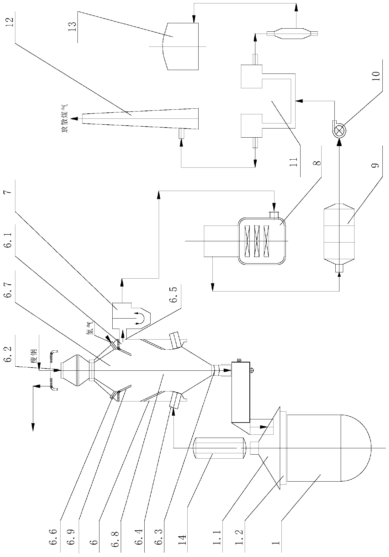
[0038] see figure 1 The system of the present invention includes a converter smelting system and a converter flue dust waste heat recovery purification conditioning system, the converter smelting system includes a converter 1 with a converter hood 1.1 and a movable skirt 1.2 and a cold material preheater 6 located above the converter 1 , the discharge port of the cold material preheater 6 is connected to the feed port on the converter hood 1.1, and the air inlet of the cold material preheater 6 is connected to the converter hood 1.1 through the vaporization cooling flue 14 The soot outlet of the cold material preheater 6 is connected to the gas outlet of the converter flue dust waste heat recovery purification conditioning system. In this embodiment, the cold material preheater includes a cold material preheater 6, and the input cold material is steel scrap.

[0039] The top of the cold material preheater 6 is provided with a material inlet 6.2, the bottom is provided with a ...

Embodiment 2

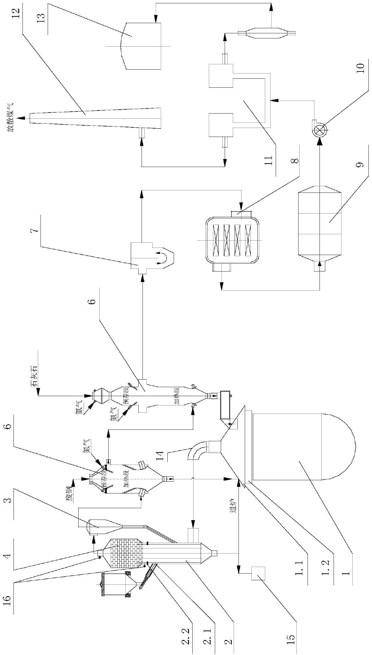
[0047] see figure 2 , and the difference from Example 1 is: the outlet of vaporization cooling flue gas 14 is connected with the air inlet of the fluidized bed gasifier 2, regenerator 4, cyclone dust collector 3 and the cold material preheater 6 , the ash outlet of the cyclone dust collector 3 is connected to the fluidized bed gasifier 2 . The material dropped into the fluidized bed gasifier 2 is medical waste; the cold material preheater 6 is two in series, and the steelmaking cold material dropped into the first cold material preheater 6 is scrap steel, The steelmaking cold material dropped into in the second cold material preheater 6 is limestone. All the other are with embodiment 1.

[0048] Wherein, the fluidized bed gasifier 2 is provided with a solid material feed port 2.1 and a liquid material injection port 2.2 for feeding medical waste or high-concentration organic waste liquid, and the top of the fluidized bed gasifier 2 is provided with There is a regenerator 4...

Embodiment 3

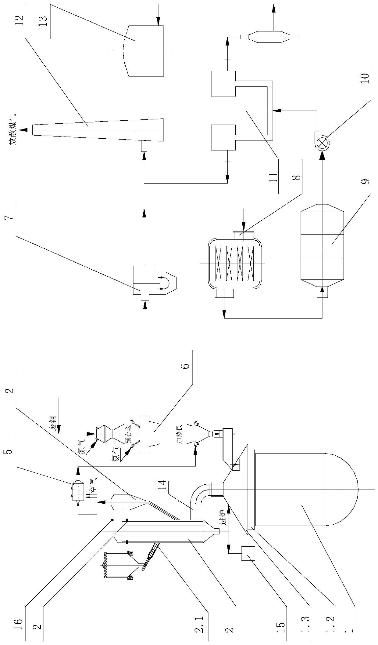
[0054] see image 3 , and the difference from Example 2 is that the regenerator 4 is canceled, the fluidized bed gasifier 2 is connected with a cold material preheater 6 through the cyclone dust collector 3, the combustion chamber 5, and the liquid material is sprayed into the inlet 2.2. The material put into the fluidized bed gasifier 2 is high-concentration organic waste liquid, and the steelmaking cold material in the cold material preheater 6 is steel scrap. All the other are with embodiment 2.

[0055] The process is different from Example 1 in that: the mixed gas from the fluidized bed reactor is first dedusted by the cyclone dust collector 3, and then sent into the cold material preheater 6 through the combustion chamber 5, and controlled to enter the cold material preheater. The mixed gas temperature of heater 6 is at 800-1000 ℃. When the combustion chamber 5 is installed, when the converter starts the oxygen blowing smelting stage, high-concentration organic waste l...


PUM


Abstract

The invention discloses a rotary kiln gas purification and waste heat recycling and utilizing system. The problems that the gas sensible heat of an existing rotary kiln is not effectively utilized, the iron loss is serious, and the like are solved. According to the technical scheme, the rotary kiln gas purification and waste heat recycling and utilizing system comprises a rotary kiln smelting system and a rotary kiln smoke waste heat recycling, purifying and conditioning system. The rotary kiln smelting system comprises a rotary kiln and a cold material preheater located above the rotary kiln,wherein the rotary kiln is provided with a rotary kiln smoke hood and a movable hood skirt. A material outlet of the cold material preheater is connected with a material inlet in the rotary kiln smoke hood, a smoke inlet of the cold material preheater is connected with a smoke outlet in the rotary kiln smoke hood through a vaporizing cooling flue, and a smoke outlet of the cold material preheateris connected with the rotary kiln smoke waste heat recycling, purifying and conditioning system. The rotary kiln gas purification and waste heat recycling and utilizing system is simple, capable of effectively recycling the rotary kiln smoke visible heat and increasing the gas recycling amount and meanwhile capable of processing high-concentration organic waste liquid and medical garbage in a harmless manner.

Description

technical field [0001] The invention relates to the field of energy saving and environmental protection of metallurgy, in particular to a converter gas purification and waste heat recovery and utilization system. Background technique [0002] During the converter steelmaking process, the carbon in the molten iron and the oxygen blown in at high temperature generate CO and a small amount of CO 2 The mixed gas becomes converter flue gas, and the purified converter flue gas is called converter gas. The converter flue gas has a large dust content (80-150g / m 3 , the main component of the soot is ferrous oxide, accounting for more than 60%), the dust content accounts for about 1% to 2% of the charge, and the temperature is as high as 1600°C, mainly composed of iron oxide, and the rest includes oxide impurities (such as calcium oxide) and other metal oxides (mainly zinc oxide). [0003] Aiming at the mechanism of soot generation in the converter steelmaking process, Bi Xiurong e...

Claims


Application Information

Patent Timeline
Patent Type & Authority Patents(China)
IPC IPC(8): C21C5/40F27D17/00
CPCC21C5/40F27D17/004F27D2017/007
Inventor 吴高明柯汉军卢丽君付本全杨超
Owner 武汉钢铁有限公司
Learn More