

Cu nano point@BN nanosphere compound, and preparation method and application thereof
A nano-dot and nano-sphere technology is applied in the field of Cu nano-dot@BN nano-sphere composite electromagnetic wave absorbing material and its preparation, achieving the effects of simple preparation process conditions, excellent electromagnetic absorption ability, and easy control.
- Summary
- Abstract
- Description
- Claims
- Application Information
AI Technical Summary
Problems solved by technology
Method used
Image


Examples
Embodiment 1
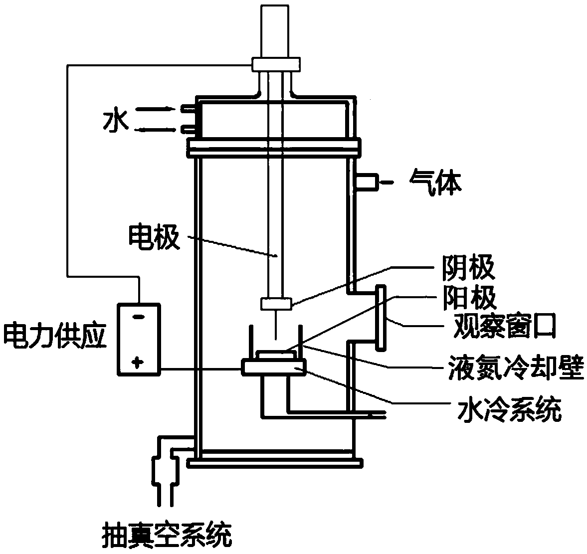
[0037] Will figure 1 The device shown is opened, tungsten is used as the cathode, and the anode target consumed is a block made of pure copper powder and boron powder (mass ratio 10:90), which is placed on a cooling water platform. A distance of 30 mm is maintained between the cathode tungsten electrode and the anode target copper-boron powder block. During the whole process, water is passed to cool the furnace body and the anode placement platform. A liquid nitrogen cooling wall was placed around the anode platform, and a distance of 10 cm was maintained between the liquid nitrogen cooling wall and the anode target. After the whole working chamber is evacuated by the vacuum system, argon and nitrogen are introduced, the partial pressure of argon is 0.5 MPa, the partial pressure of nitrogen is 3.0 MPa, the DC power supply is connected, and the voltage is 40 V. During the arc discharge process, adjust the working current and voltage to keep relatively stable. The Cu nanodots...
Embodiment 2
[0039] Will figure 1 The device shown is opened, tungsten is used as the cathode, and the anode target consumed is a block made of pure copper powder and boron powder (mass ratio 20:80), which is placed on a cooling water platform. A distance of 2 mm was maintained between the cathode tungsten electrode and the anode target copper-boron powder block. During the whole process, water is passed to cool the furnace body and the anode placement platform. A liquid nitrogen cooling wall was placed around the anode platform, and a distance of 5 cm was kept between the liquid nitrogen cooling wall and the anode target. After the whole working chamber is evacuated by the vacuum system, argon and nitrogen are introduced, the partial pressure of argon is 0.01 MPa, the partial pressure of nitrogen is 0.1 MPa, the DC power supply is connected, and the voltage is 10 V. During the arc discharge process, adjust the working current and voltage to keep relatively stable. The Cu nanodots@BN na...
Embodiment 3
[0041] Will figure 1 The device shown is opened, tungsten is used as the cathode, and the anode target consumed is a block made of pure copper powder and boron powder (mass ratio 15:85), which is placed on a cooling water platform. A distance of 10 mm was maintained between the cathode tungsten electrode and the anode target copper-boron powder block. During the whole process, water is passed to cool the furnace body and the anode placement platform. A liquid nitrogen cooling wall was placed around the anode platform, and a distance of 7 cm was maintained between the liquid nitrogen cooling wall and the anode target. After the whole working chamber is evacuated by the vacuum system, argon and nitrogen are introduced, the partial pressure of argon is 0.1 MPa, the partial pressure of nitrogen is 1.0 MPa, the DC power supply is connected, and the voltage is 20 V. During the arc discharge process, adjust the working current and voltage to keep relatively stable. The Cu nanodots...
PUM
| Property | Measurement | Unit |
|---|---|---|
| Diameter | aaaaa | aaaaa |
| Diameter | aaaaa | aaaaa |
Abstract
Description
Claims
Application Information