
Preparation method of bandgap longitudinal gradient distributed Ga2O3 thin film co-doped with Al and Fe

A gradient distribution and co-doping technology, applied in electrical components, circuits, semiconductor devices, etc., can solve the problems of uneven electric field distribution, large leakage current, unstable electrical performance, etc., achieving superior performance, dense film, and easy operation. Effect

Active Publication Date: 2018-11-23
北京镓和半导体有限公司
View PDF5 Cites 1 Cited by
  • Summary
  • Abstract
  • Description
  • Claims
  • Application Information

AI Technical Summary

Problems solved by technology

However, when preparing GaO-based field effect transistors, Ga 2 o 3 Between the channel film and the heterogeneous high-resistance, high-K dielectric and Ga 2 o 3 A complex interface is easily formed between the channel film and the heterogeneous substrate, causing problems such as excessive leakage current, uneven electric field distribution, and unstable electrical properties under high electric field strength.

Method used


Image

  • Preparation method of bandgap longitudinal gradient distributed Ga2O3 thin film co-doped with Al and Fe
  • Preparation method of bandgap longitudinal gradient distributed Ga2O3 thin film co-doped with Al and Fe
  • Preparation method of bandgap longitudinal gradient distributed Ga2O3 thin film co-doped with Al and Fe

Examples


Embodiment 1

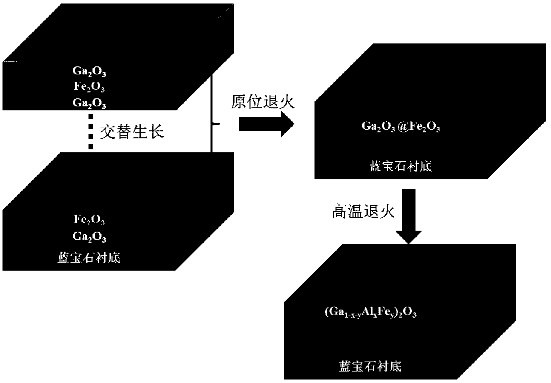
[0055] This embodiment provides a longitudinal gradient distribution of bandgap Al and Fe co-doped Ga 2 o 3 The preparation method of thin film, comprises the following steps:

[0056] 1) With the cleaned c-plane sapphire as the substrate, a layer of Ga was first deposited on the substrate by laser molecular beam epitaxy 2 o 3 ultra-thin layer, and then deposited a layer of Fe 2o 3 Ultra-thin layer, deposited Ga 2 o 3 with Fe 2 o 3 The number of laser pulses for ultra-thin layers is selected: 200 / 20, 200 / 40, 200 / 60, 200 / 80, 200 / 100; alternate growth, so cycle 20 times;

[0057] Among them, the specific conditions for laser molecular beam epitaxy are: the background vacuum is 1×10 -6 Pa, substrate temperature is 750℃, oxygen pressure is 5×10 -1 Pa, the laser energy is 400mJ, the laser pulse frequency is 1Hz, and the distance between the target and the substrate is 4.5cm;

[0058] 2) Deposit Ga 2 o 3 and Fe 2 o 3 After the ultra-thin layer, in-situ annealing at 75...

Embodiment 2

[0065] This embodiment provides a longitudinal gradient distribution of bandgap Al and Fe co-doped Ga 2 o 3 The preparation method of thin film, comprises the following steps:

[0066] 1) With the cleaned c-plane sapphire as the substrate, a layer of Ga was first deposited on the substrate by laser molecular beam epitaxy 2 o 3 ultra-thin layer, and then deposited a layer of Fe 2 o 3 Ultra-thin layer, deposited Ga 2 o 3 with Fe 2 o 3 The number of laser pulses for the ultra-thin layer is selected: 100 / 30 alternate growth, so that the cycle is 100 cycles;

[0067] Among them, the specific conditions for laser molecular beam epitaxy are: the background vacuum is 1×10 -6 Pa, substrate temperature is 750℃, oxygen pressure is 5×10 -1 Pa, the laser energy is 400mJ, the laser pulse frequency is 1Hz, and the distance between the target and the substrate is 4.5cm;

[0068] 2) Deposit Ga 2 o 3 and Fe 2 o 3 After the ultra-thin layer, in-situ annealing at 750°C for 30 minut...

Embodiment 3

[0071] This embodiment provides a longitudinal gradient distribution of bandgap Al and Fe co-doped Ga 2 o 3 The difference between the method of making the film and Example 2 is that the annealing temperature in step 3) is 800°C.


PUM

PropertyMeasurementUnit
Thicknessaaaaaaaaaa

Abstract

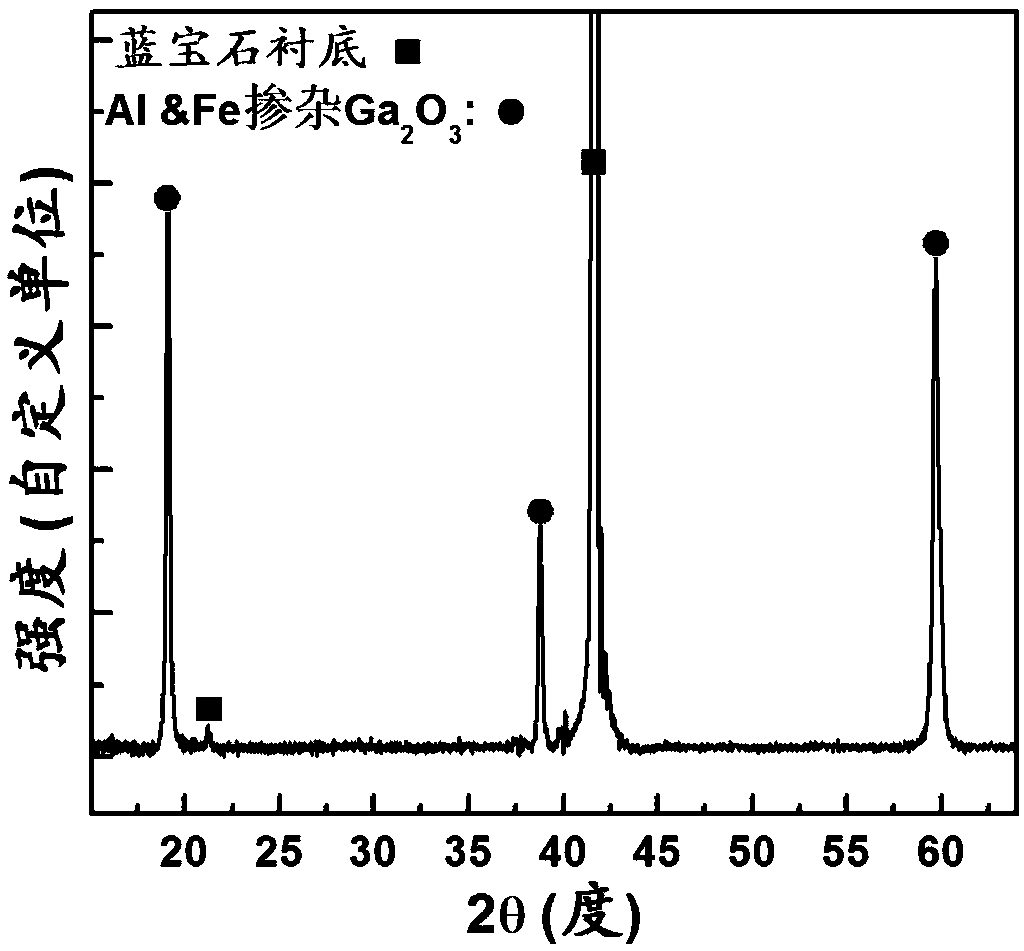
The invention relates to a preparation method of a bandgap longitudinal gradient distributed Ga2O3 thin film co-doped with Al and Fe. According to the preparation method, the Ga2O3 thin film is prepared by taking Alpha-Al2O3 single crystal as a substrate, alternatively depositing Ga2O3 and Fe2O3 superthin layers by laser molecular beam epitaxy and then performing annealing. The preparation methodis simple in process, high in process controllability and good in repeatability and is easy to prepare, and large-area preparation can be achieved; and Al constituent in the prepared thin film is distributed in a longitudinal and gradient way, and the thin film is good in crystallinity and uniform in surface and is compact.

Description

technical field [0001] The invention relates to the technical field of bandgap engineering and wide bandgap optoelectronic devices, in particular to an Al and Fe co-doped Ga with a longitudinal gradient distribution of the bandgap 2 o 3 Thin film preparation techniques. Background technique [0002] Because the ozone layer in the atmosphere has a strong absorption effect on the ultraviolet light in the band between 200-280nm, the ultraviolet radiation in this band that reaches the ground is almost attenuated to zero near the sea level, so the light in this band is called solar radiation. Blind ultraviolet light, and signal detection for this band is called solar-blind ultraviolet detection. Because it is not affected by the sunlight background signal, the detection sensitivity of solar-blind ultraviolet light signal is extremely high. The solar-blind ultraviolet detection technology has become a new type of military-civilian dual-use photoelectric detection technology deve...

Claims


Application Information

Patent Timeline
IPC IPC(8): H01L31/0304H01L31/18
CPCH01L31/03042H01L31/18
Inventor 唐为华崔蔚
Owner 北京镓和半导体有限公司
Learn More