Manufacturing method for silicon nitride coating

A technology of silicon nitride coating and manufacturing method, applied in chemical instruments and methods, coating, crystal growth, etc., can solve the problems of reducing the quality of silicon wafers, increasing the manufacturing cost of silicon wafers, and contamination of the bottom and side of silicon ingots , to achieve the effect of reducing production cost, improving product quality, and avoiding the phenomenon of sticking pot

Inactive Publication Date: 2018-11-30
JINKO SOLAR CO LTD +1
View PDF6 Cites 2 Cited by
  • Summary
  • Abstract
  • Description
  • Claims
  • Application Information

AI Technical Summary

Problems solved by technology
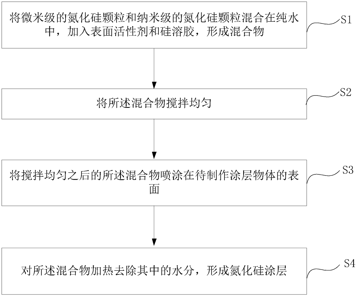
[0003] In the prior art, the silicon nitride sprayed in the quartz crucible used for solar polysilicon ingots is all micron-sized, and since silicon nitride is a particulate matter, the process for making this silicon nitride coating includes: Make a slurry first, and then spray it on the inner wall of the crucible. The particles in the silicon nitride coating obtained in this way are easy to form holes. Silicon coating affects the compactness of the coating and forms "channels". Impurity elements such as Fe, Al, and O in the crucible will diffuse into the silicon material, causing pollution to the bottom and sides of the silicon ingot, resulting in a red zone, and ultimately affecting the silicon wafer quality, and the obtained polycrystalline ingot coating has poor compactness and a high proportion of silicon ingot impurities, which will cause a high proportion of broken wires and line marks during diamond wire cutting, reducing the quality of silicon wafers and Increased manufacturing cost of silicon wafers

Method used


Image

  • Manufacturing method for silicon nitride coating
  • Manufacturing method for silicon nitride coating
  • Manufacturing method for silicon nitride coating

Examples


example 1

[0047] [Example 1] Weigh 650g of silicon nitride powder with D50 (50% average particle size, the same below) of 2.5um, 50g of silicon nitride powder with D50 of 1.5nm, and measure 2300ml with a graduated cylinder. Water, measure 300ml of ion-free silica sol and 5g fatty alcohol polyoxyethylene ether (AEO) with a graduated cylinder, then mix the above materials into a graduated cylinder containing a stirrer, stir quickly for 3 minutes, and continue stirring at a medium speed at 220rpm 5 minutes;

[0048] Remove the quartz crucible package and place it flat on the bottom of the high-purity isocratic graphite. Turn on the crucible and heat the rotating table. Use the infrared tester to test the temperature of the crucible inner wall to 100 degrees Celsius. Then spray the silicon nitride on the inner wall area of ​​the crucible. After spraying the silicon nitride slurry, heat it on the crucible heating rotary table for 30 minutes to ensure that the water in the crucible inner wall co...

example 2

[0049] [Example 2] Weigh 700g of silicon nitride powder with D50 of 2.75um, 65g of silicon nitride powder with D50 of 0.75nm, measure 2700ml of pure water with a graduated cylinder, and measure 300ml of ion-free silica sol with a graduated cylinder. , 7g fatty alcohol polyoxyethylene ether (AEO), then mix the above materials into a graduated cylinder containing a stirrer, stir quickly for 4 minutes, and continue stirring at medium speed for 5 minutes at 250rpm;

[0050] Remove the quartz crucible package and place it flat on the bottom of the high-purity isocratic graphite. Turn on the crucible and heat the rotating table. Use the infrared tester to test the temperature of the crucible inner wall to 100 degrees Celsius. Then spray the silicon nitride on the inner wall area of ​​the crucible. After spraying the silicon nitride slurry, heat it on the crucible heating rotary table for 30 minutes to ensure that the water in the crucible inner wall coating is fully evaporated. Finally,...

example 3

[0051] [Example 3] Weigh 730g of silicon nitride powder with D50 of 2.05um, 55g of silicon nitride powder with D50 of 0.95nm by electronic weighing, measure 3000ml of deionized water with a graduated cylinder, and measure 350ml of non-ionized silicon with a graduated cylinder Sol, 7.5g fatty alcohol polyoxyethylene ether (AEO), then mix the above materials into a graduated cylinder containing a stirrer, stir quickly for 4 minutes, and continue stirring at medium speed for 5 minutes at 250rpm;

[0052] Remove the quartz crucible package and place it flat on the bottom of the high-purity isocratic graphite. Turn on the crucible and heat the rotating table. Use the infrared tester to test the temperature of the crucible inner wall to 100 degrees Celsius. Then spray the silicon nitride on the inner wall area of ​​the crucible. After spraying the silicon nitride slurry, heat it on the crucible heating rotary table for 30 minutes to ensure that the water in the crucible inner wall coati...


PUM


Abstract

The invention discloses a manufacturing method for a silicon nitride coating. The manufacturing method comprises the following steps: mixing micron-sized silicon nitride particles and nano-sized silicon nitride particles in purified water, and adding a surfactant and a silica sol so as to form a mixture; uniformly mixing the mixture under stirring; spraying the uniformly-mixed mixture onto the surface of a to-be-coated object; and heating the mixture to remove moisture therein so as to form the silicon nitride coating. The silicon nitride coating manufactured by using the above-mentioned method has the following advantages: through mutual cooperation of the nano-sized silicon nitride particles and the micron-sized silicon nitride particles in the interior of the silicon nitride coating, gaps among particles are smaller, and the compactness of the silicon nitride coating is improved, so the problem of low compactness due to only use of the micron-sized silicon nitride particles for manufacturing of the silicon nitride coating in the prior art is avoided; and impurities can be avoided from diffusing into a silicon material from the gaps in the silicon nitride coating by penetrating through a crucible in the process of ingotting, and the phenomenon of sticking of the impurities to the crucible is avoided from occurrence, so the quality of a product is improved, and the cost of production is reduced.

Description

Technical field [0001] The invention belongs to the technical field of photovoltaic equipment manufacturing, and particularly relates to a manufacturing method of a silicon nitride coating. Background technique [0002] In the process of polycrystalline ingot casting, it is necessary to use a quartz crucible as an ingot container. Because quartz reacts with polycrystalline silicon at high temperature and produces adhesion, impurities such as Fe, Al, O enter the silicon material and the viscous crucible will crack and cause cracking. Therefore, the quartz crucible needs to be coated with a silicon nitride coating before the ingot is cast to prevent the liquid phase silicon from chemically reacting with the quartz to cause sticking, and it also prevents metal impurities and oxygen from entering the silicon material. [0003] In the prior art, the silicon nitride sprayed in the quartz crucible used for solar polysilicon ingots is all micron-sized. Since silicon nitride is a particulat...

Claims


Application Information

Patent Timeline
IPC IPC(8): C03C17/00C30B28/06C30B29/06
CPCC03C17/004C03C17/007C03C17/009C03C2217/45C03C2217/475C30B28/06C30B29/06
Inventor 周慧敏冷金标龙昭钦
Owner JINKO SOLAR CO LTD
Why Eureka
Try Eureka