Grouting electric heating tank system for magnesium catalytic furnace chamber CO2 combustion and carbon fixation

An electric heating tank and CO2 technology, applied in the direction of combustion using catalytic materials, combustion methods, combustion types, etc., can solve the problems of lagging scientific research pace, aggravation, and increasing nitric acid gas flue gas emissions, etc.

Inactive Publication Date: 2019-01-04
管理
View PDF1 Cites 4 Cited by
  • Summary
  • Abstract
  • Description
  • Claims
  • Application Information

AI Technical Summary

Problems solved by technology

[0002] At present, the known oil and gas combustion technologies all adopt the traditional complete air combustion. "Because most of the 78.9% inert gas in the air is nitrogen, not only does not help combustion, but also 'takes' a large amount of nitrogen from the furnace." Oxygen (every 1 ton equivalent of N in the combustion product reacts to generate NO 2 , it needs to consume more than 2.29 tons of oxygen, resulting in an increase of about 11,000 m in the non-oxygen excess air supply of the inert gas blown into the boiler furnace by the blower 3 , based on the exhaust gas temperature of 200°C at 15°C, the additional incremental heat exhaust gas is 18,500 nm 3 , the sensible heat loss is as high as 1.13 million kcal) and generate nitrogen oxides that are extremely harmful to human health (according to a research report by an authoritative organization in Western Europe in the 1990s that sounded the alarm to all mankind, if according to the end of the 20th century If the nitrogen oxide pollution situation in Western Europe is left unchecked, then the males in this environment will gradually lose their reproductive ability), and at the same time, the flue gas emission of nitric acid gas will also be greatly increased.”
Therefore, the national “coal-to-gas” work over the past few years has been seriously lagging behind in scientific research in this area. It is clear that the culprit of pollution that really causes smog in the process of natural gas combustion is nitric acid gas. The "persistent disease" of environmental pollution that cannot be avoided by people in the whole society and must be eradicated... The current oil and gas burners (even if oxygen production technology is used to supply wind It still consumes the oxygen of the earth's air without exception, it can only aggravate the crisis of "a sharp drop in oxygen concentration" in the earth's atmosphere), and has been unable to adapt to ZL201210566497.4 "A Mg Catalyzed Water-based Combustion-supporting Coal, Gas Boilers, kilns and furnaces with oil, low carbon, sulfur and nitric emissions" The national and even global development of new combustion science is bound to be based on the revolutionary demands and rapid quantification of energy (according to statistics, China alone has 620,000 coal-fired boilers and about 460,000 industrial boilers , with a total capacity of 2 million steam tons / hour, and it is estimated that industrial boilers with a capacity of less than 20 steam tons / hour are the targets of coal-to-gas conversion, accounting for 85% of the total, reaching as many as 530,000 units; in addition, there are normal and low pressure seasons for heating in the north The boilers in operation are estimated to have a total capacity of 600,000 steam tons per hour, and there are 1.5 million large and small wall-hung boilers, etc., which are the vast market for coal-to-gas conversion in the future), which must be revolutionized and popularized with this energy revolution to meet The need for a national ultra-energy-saving and environmental protection major replacement

Method used


Image

  • Grouting electric heating tank system for magnesium catalytic furnace chamber CO2 combustion and carbon fixation
  • Grouting electric heating tank system for magnesium catalytic furnace chamber CO2 combustion and carbon fixation
  • Grouting electric heating tank system for magnesium catalytic furnace chamber CO2 combustion and carbon fixation

Examples


Embodiment Construction

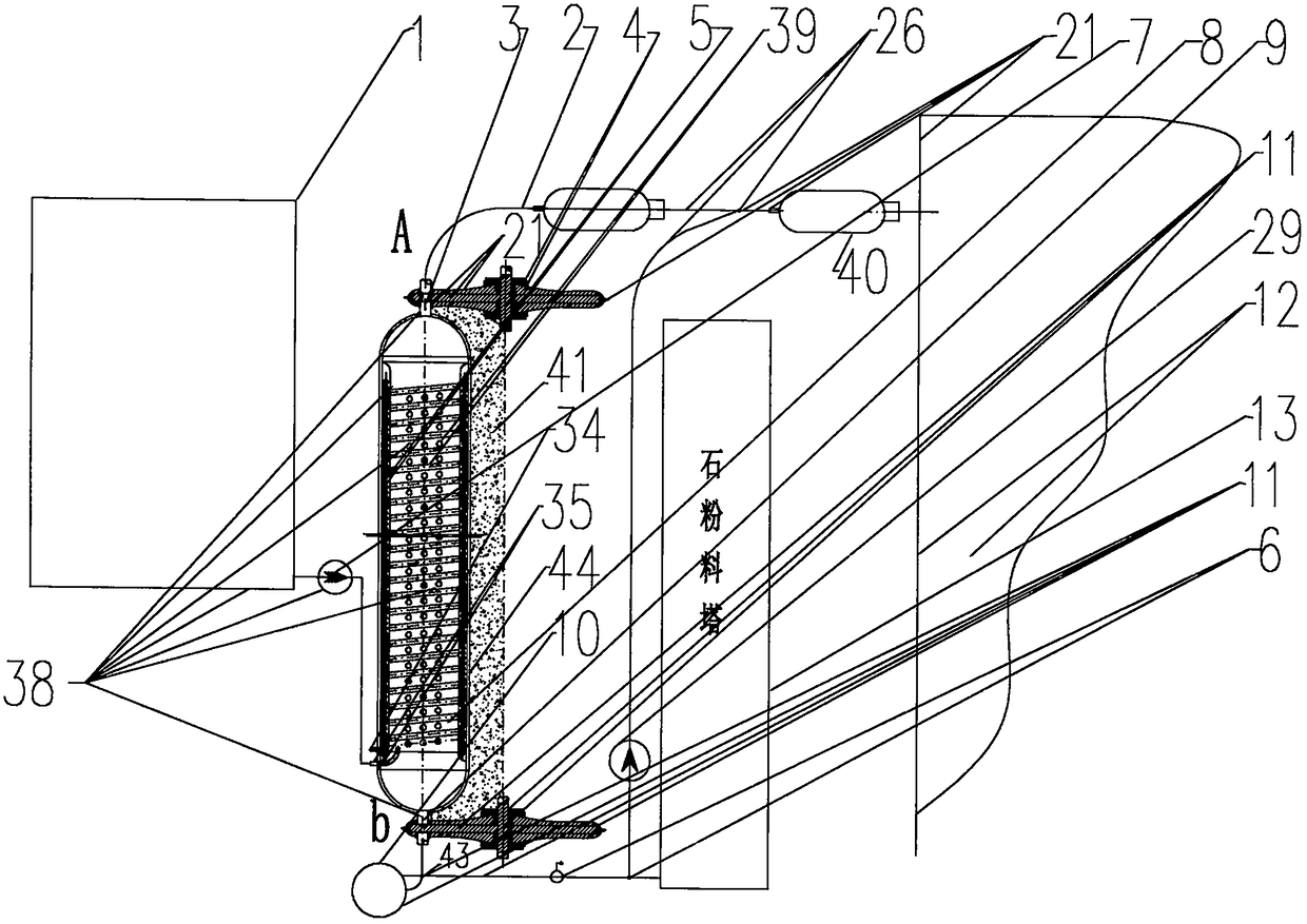
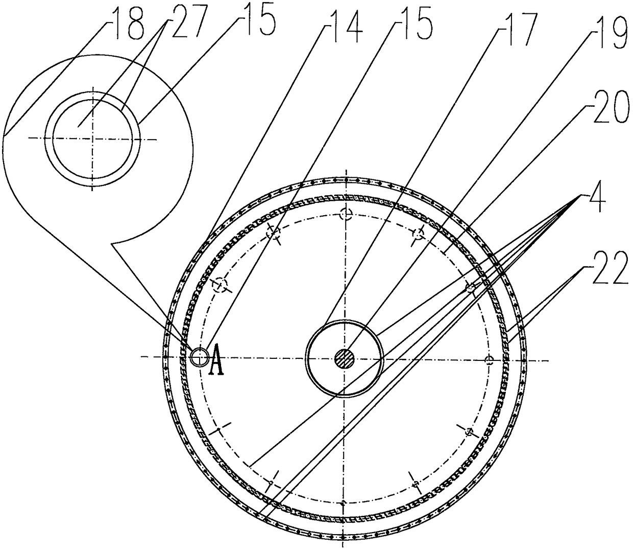
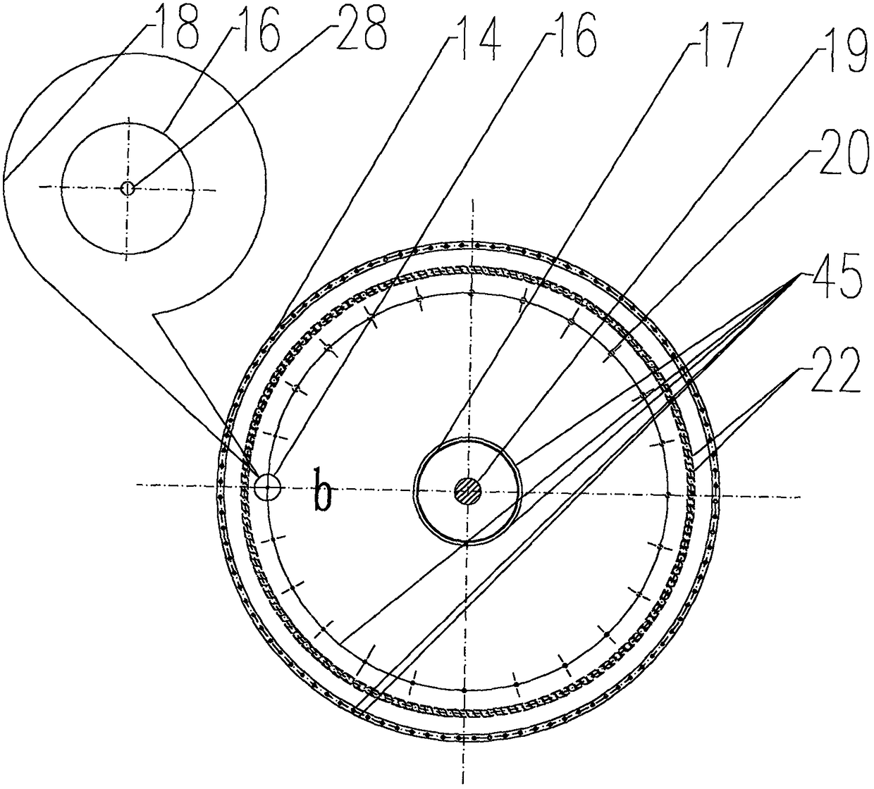
[0012] exist figure 1 Among them, in the grouting electric heating tank system 38, the electric heating super-pressure slag gas separation tank 44 is the core, and the coal-water slurry pump 7 on the upstream connecting pipeline 50 is connected to the source head of the coal-water slurry tank 1. Into the upper curved spray grouting inlet 35 of the tank 44 of the system 38, the downstream gas outlet rotary valve assembly 21 on the gas outlet 15, and the steam valve core of the gas outlet rotary valve 4 of the assembly 21 "big "The hole 27 is connected to the injection pipe 2 and the three-way pipe system 26 through the pressure transformer 40, and the pipe system 26 passes through the stone powder frequency conversion pump 29 to lead the magnesium steam generation stone powder in the stone powder material tower 13 to the furnace of the ZL201210566497.4 boiler in one direction. 12 away; the slag discharge outlet 9 at the bottom of the electrothermal overpressure slag gas separatio...


PUM


Abstract

Provided is a grouting electric heating tank system technology for magnesium catalytic furnace chamber CO2 combustion and carbon fixation. The technology is a fuel gas-fired boiler of a ZL201210566497.4 patented product and used as a matching object, a coal water slurry electrothermal over-pressure slag gas separation tank is provided with a gas outlet rotary disc valve assembly and a slag discharge outlet rotary disc valve assembly to ensure safe and normal gas production and slagging of the grouting electric heating tank system, gas and slag separation is achieved and combined with dolomitepowder roasting or fluidized bed rich powder to produce magnesium vapors for supply air-free combustion matched with boilers, which is used for the purposes that the big and small boilers in active duty are remade and manufactured, the energy is saved by 50-60%, the carbon emission is reduced by more than 50% and nitrogen oxides are reduced by more than 95%, and the system must produce huge impetus for energy reform of magnesium catalysis of China.

Description

technical field [0001] The invention relates to a magnesium catalytic furnace CO 2 Slurry electric heating tank system technology for combustion and carbon fixation is an original and innovative new combustion mechanism in the patent No. ZL201210566497.4 "A Mg-catalyzed water-based combustion-supporting coal, gas, oil low-carbon sulfur-nitrate emission boiler kiln furnace" On the basis of coal-water slurry electric heating overpressure slag-gas separation tank, turntable valves are installed before and after to ensure the safety of gas and slag separation, combined with dolomite powder roasting or magnesium steam produced by fluidized bed powder-enriched air-free for boilers Combustion-supporting combustion, the large and small active boilers are modified and manufactured as Mg catalyzed water-based combustion-supporting coal, gas, oil, low-carbon, sulfur and nitrate emission boilers with water, coal, electric heating, overpressure gas supply and CO 2 Combustion carbon seques...

Claims


Application Information

Patent Timeline
IPC IPC(8): F23C13/08
CPCF23C13/08
Inventor 管理
Owner 管理
Why Eureka
Try Eureka