Device with energy conservation and emission reduction effects and simultaneous desulfurization and denitrification effects on flue gas and special coating for device

A technology for desulfurization, denitrification, energy saving and emission reduction. It is used in coatings, combined devices, and greenhouse gas reduction. It can solve problems such as air pollution and large ash content, and achieve the effects of environmental protection, high dust removal efficiency and short dust removal time.

Pending Publication Date: 2019-02-22
YIXING HAINA ENVIRONMENTAL ENG
View PDF13 Cites 2 Cited by
  • Summary
  • Abstract
  • Description
  • Claims
  • Application Information

AI Technical Summary

Problems solved by technology

[0004] With the progress of the society and the requirements of environmental protection, the flue gas after combustion and heating is exhausted out of the chimney and discharged into the atmosphere after recovering heat. The flue gas contains a large amount of ash, and also contains alkali metals, sulfur, etc., which will cause air pollution. Therefore, the research and development of a A device with good energy reduction and emission reduction combined with desulfurization and denitrification has become a technical problem to be solved urgently by those skilled in the art

Method used


Image

  • Device with energy conservation and emission reduction effects and simultaneous desulfurization and denitrification effects on flue gas and special coating for device
  • Device with energy conservation and emission reduction effects and simultaneous desulfurization and denitrification effects on flue gas and special coating for device
  • Device with energy conservation and emission reduction effects and simultaneous desulfurization and denitrification effects on flue gas and special coating for device

Examples


Embodiment 1

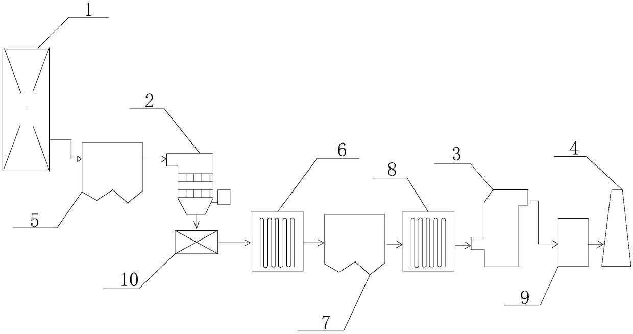
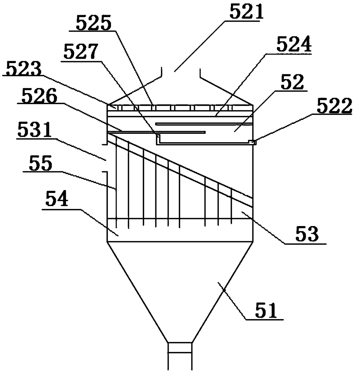
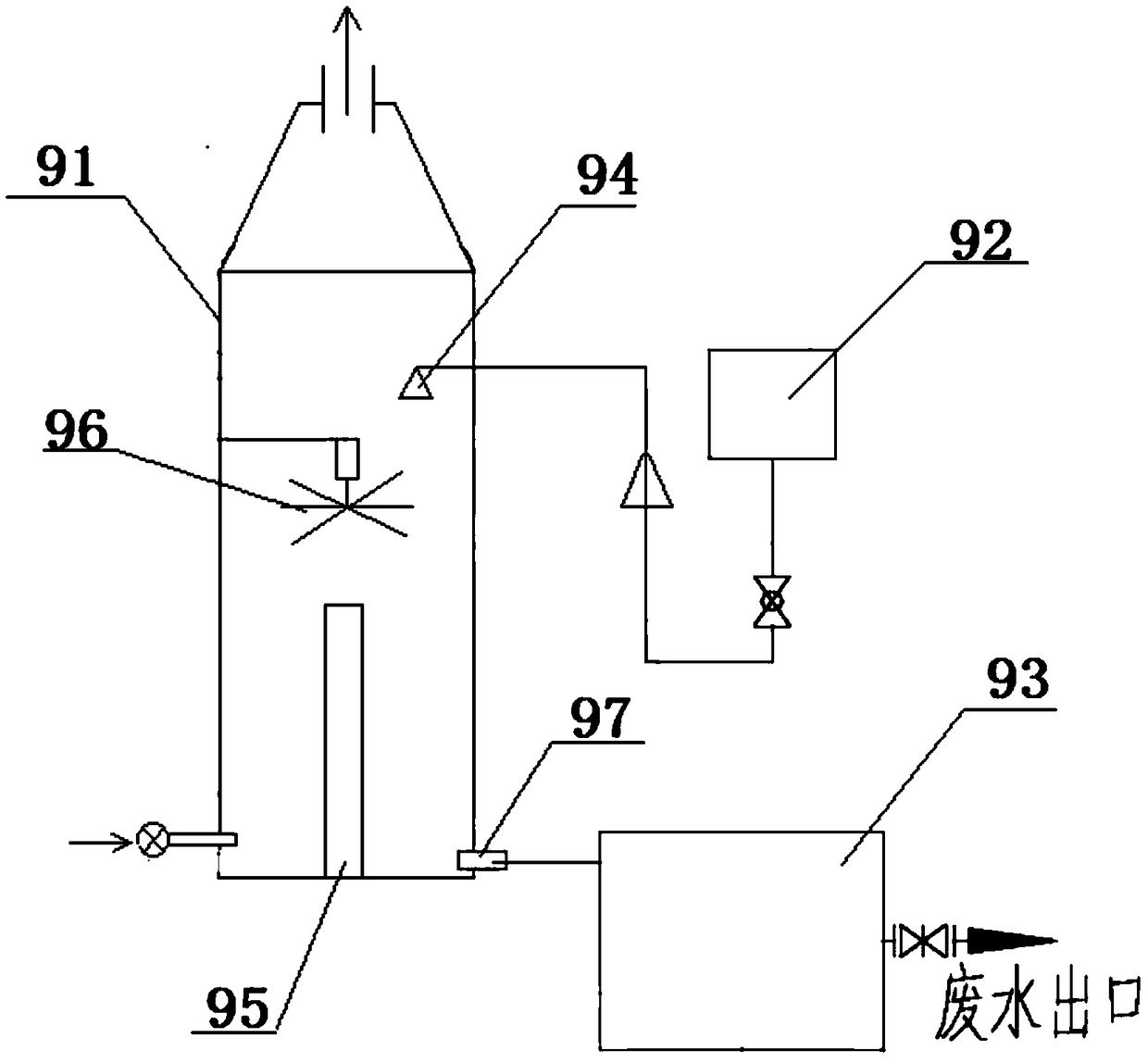
[0047] This embodiment provides an energy-saving and emission-reducing flue gas simultaneous desulfurization and denitrification device, the structure of which is as follows Figure 1-3 As shown, it includes boiler 1, denitrification device 2, desulfurization device 3 and chimney 4, and is characterized in that: the output end of boiler 1 is connected with the input end of denitrification device 2 through the first dust collector 5, and the output end of denitrification device 2 is connected with Air preheater 10, the output end of air preheater 10 is connected with first heat exchanger 6, the output end of first heat exchanger 6 is connected with the input end of second dust remover 7, the output of second dust remover 7 end is connected with the second heat exchanger 8 through the fan, the output end of the second heat exchanger 8 is connected with the desulfurization device 3, the output end of the desulfurization device 3 is connected with the lye absorption device 9, and t...

Embodiment 2

[0058] This embodiment provides a special coating for the device in Example 1, the coating comprises the following components in parts by mass:

[0059] Silicone modified epoxy resin: 15 parts, polyaryl ether sulfone ketone modified resin: 10 parts, black silicon carbide: 5 parts, leveling agent: 1 part, filler: 1 part, plasticizer: 5 parts, contact Variable agent: 2 parts, precipitated barium sulfate: 5 parts, pigment: 1 part, dispersant: 3 parts, curing agent: 10 parts, compound rare earth: 0.01 part;

[0060] Silicone-modified epoxy resin includes the following components in terms of mass percentage: deionized water: 13%, dibutyltin dilaurate: 10%, methyltriethoxysilane: 10%, and the balance is epoxy resin, above The sum of each component is 100%;

[0061] The plasticizer is dioctyl phthalate; the pigment is titanium dioxide; the dispersant is sodium tripolyphosphate; the curing agent is a modified polyamide curing agent; the thixotropic agent is organic montmorillonite an...

Embodiment 3

[0073] This embodiment provides a special coating for the device in Example 1, the coating comprises the following components in parts by mass:

[0074] Silicone modified epoxy resin: 20 parts, polyarylethersulfone ketone modified resin: 12 parts, black silicon carbide: 7 parts, leveling agent: 2 parts, filler: 3 parts, plasticizer: 5-7 parts , thixotropic agent: 4 parts, precipitated barium sulfate: 7 parts, pigment: 3 parts, dispersant: 5 parts, curing agent: 13 parts, composite rare earth: 0.03 parts;

[0075] Silicone-modified epoxy resin includes the following components in terms of mass percentage: deionized water: 18%, dibutyltin dilaurate: 13%, methyltriethoxysilane: 14%, and the balance is epoxy resin, above The sum of each component is 100%;

[0076] The plasticizer is tricresyl phosphate; the pigment is iron oxide red; the dispersant is sodium tetrapolyphosphate; the curing agent is a modified polyamide curing agent; the thixotropic agent is organic montmorillonite...


PUM

PropertyMeasurementUnit
particle diameteraaaaaaaaaa
thicknessaaaaaaaaaa
thicknessaaaaaaaaaa

Abstract

The invention discloses a device with the energy conservation and emission reduction effects and the simultaneous desulfurization and denitrification effects on flue gas. The device comprises a boiler, a denitrification device body, a desulfurization device body and a chimney, the output end of the boiler is connected to the input end of the denitrification device body through a first dust remover, the output end of the denitrification device body is connected with an air preheater, the output end of the air preheater is connected with a first heat exchanger, the output end of the first heat exchanger is connected to the input end of a second dust remover, the output end of the second dust remover is connected to a second heat exchanger through a fan, the output end of the second heat exchanger is connected with the desulfurization device body, the output end of the desulfurization device is connected with an alkali liquor absorption device, and the output end of the alkali liquor absorption device is connected to the chimney. The device has the advantages of being simple and compact in structure, obvious in effect, good in energy conservation and emission reduction effects and denitrification and desulfurization effects and low in cost. The invention further discloses a coating of the device. The coating of the device is further designed and has good chemical reagent resistance, and the service life of the device is prolonged.

Description

technical field [0001] The invention relates to a desulfurization and denitrification device, in particular to a simultaneous desulfurization and denitrification device for energy saving and emission reduction of flue gas and a special coating for the device. Background technique [0002] Thermal energy is widely used, it can be directly applied in life and production, such as air conditioning, metallurgy, textile, chemical industry, papermaking and other fields, and can also be converted into other forms of energy, such as electrical energy, mechanical energy, etc. Thermal energy is burned by dyes It is formed by converting chemical energy into water vapor or flue gas. The fuel is burned to convert the chemical energy in it into the heat energy carried by the combustion product. The carrier is flue gas; [0003] In recent years, the average annual output of raw coal is about 3.05 billion tons, and the raw coal for power generation is 1.56 billion tons. The thermal power gen...

Claims


Application Information

Patent Timeline
Patent Type & Authority Applications(China)
IPC IPC(8): B01D50/00B01D53/48B01D53/56B01D53/75B01D53/76B01D53/78F23J15/02F23J15/04F23J15/06C09D163/00C09D181/06C09D7/61C09D7/62C09D7/63C09D7/65C08G59/14
CPCB01D53/48B01D53/56B01D53/75B01D53/76B01D53/78F23J15/025F23J15/04F23J15/06C09D7/62C09D7/63C09D7/65C09D163/00C08G59/1438C09D7/61F23J2217/40F23J2215/20F23J2215/10B01D2258/0283C08K2201/014C08K2003/3009B01D50/40C08L81/06C08K13/06C08K3/40C08K3/34C08K3/30C08K3/346C08K3/36C08K5/12Y02E20/30Y02P20/10
Inventor 张忠其张栩婕
Owner YIXING HAINA ENVIRONMENTAL ENG
Why Eureka
Try Eureka