Programmable impedance adaptive laser diode driving module
A laser diode and drive module technology, applied in lasers, laser parts, semiconductor lasers, etc., can solve the problems of laser diode damage, no over-current power-off and over-temperature power-off protection functions, and achieve effective judgment and efficient work. Effect
- Summary
- Abstract
- Description
- Claims
- Application Information
AI Technical Summary
Problems solved by technology
Method used
Image
Examples
Embodiment 1
[0039] Example 1 Overall structure of the present invention
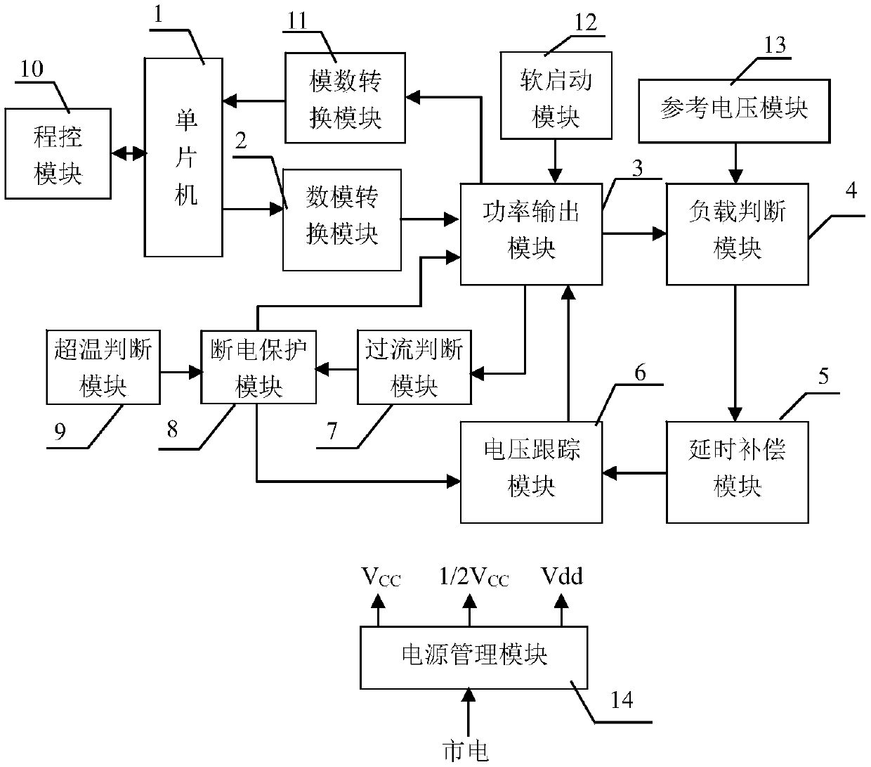
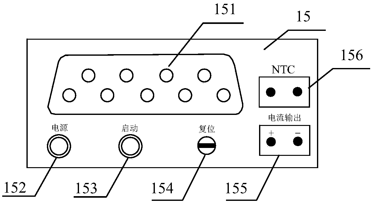
[0040] The overall structure of the present invention is as figure 1 As shown, a programmable impedance adaptive laser diode drive module has a single-chip microcomputer module 1, a digital-to-analog conversion module 2, a power output module 3, a load judgment module 4, a delay compensation module 5, a voltage tracking module 6, an overcurrent Judgment module 7, power-off protection module 8, over-temperature judgment module 9, program control module 10, analog-to-digital conversion module 11, soft start module 12, reference voltage module 13, power management module 14 and front panel 15; among them, single-chip microcomputer 1 respectively It is connected to the program control module 10, the analog-to-digital conversion module 11, and the digital-to-analog conversion module 2. The digital-to-analog conversion module 2 is connected to the power output module 3, the soft start module 12 is connected to the power outpu...
Embodiment 2
[0041] Embodiment 2 The power output module of the present invention
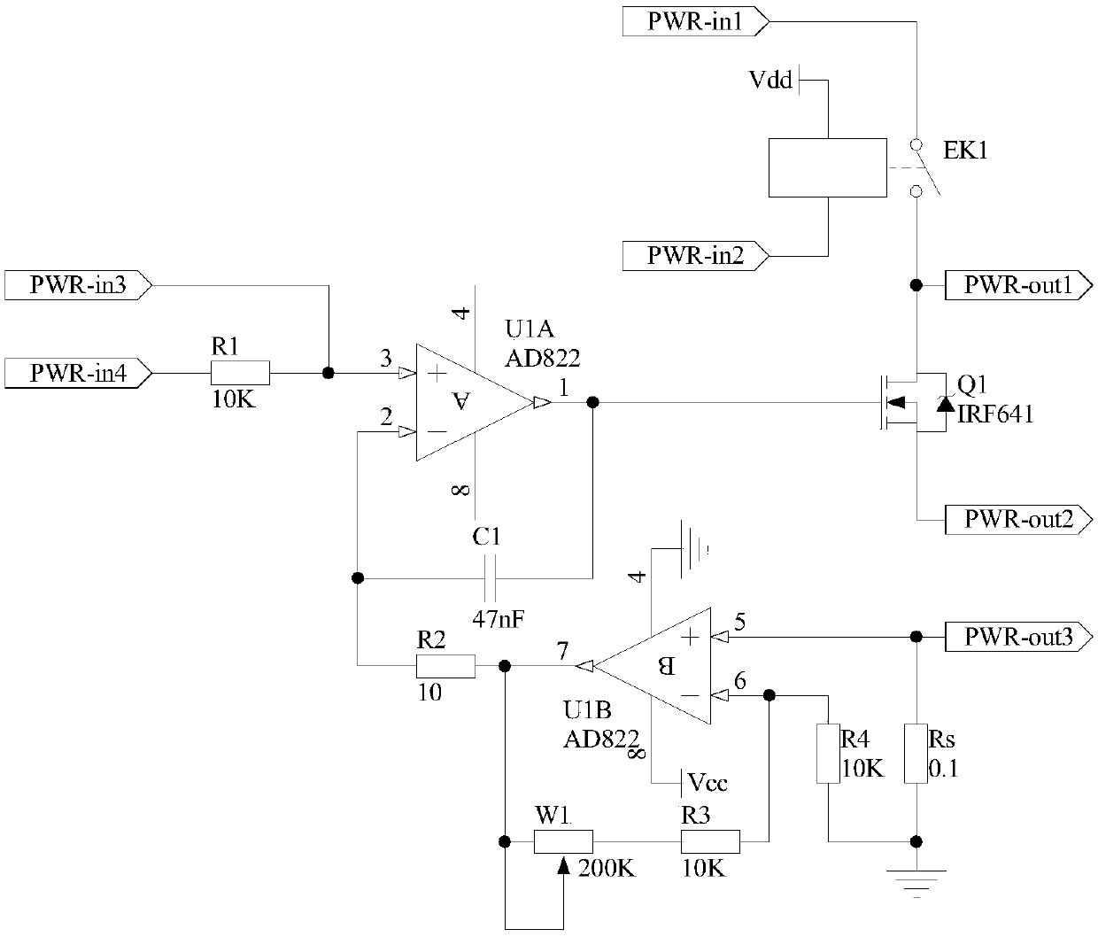
[0042] The principle circuit diagram of the power output module 3 is as follows image 3 As shown, one end of the switch of the relay EK1 is used as the first input end of the power output module 3, marked as port PWR-in1, and the other end is connected to the drain of the field effect transistor Q1, and used as the first output of the power output module 3. Terminal, marked as port PWR-out1, one end of the coil of the relay EK1 is connected to the power supply Vdd, and the other end is used as the second input terminal of the power output module 3, marked as port PWR-in2, the gate of the field effect transistor Q1 and the operational amplifier The output terminal of U1A is connected, the source is used as the second output terminal of the power output module 3, marked as port PWR-out2, one end of the resistor R1 is connected to the non-inverting input terminal of the operational amplifier U1A, and used as the ...
Embodiment 3
[0044] Embodiment 3 The load judgment module of the present invention
[0045] The principle circuit of the load judgment module 4 is as follows Figure 4 As shown, the non-inverting input terminal of the operational amplifier U2A is used as the first input terminal of the load judgment module 4, denoted as port Vjdg-in1, which is connected to the port PWR-out1 of the power output module 3, and the inverting input terminal of the operational amplifier U2A is connected to The output end of the operational amplifier U2A is connected to one end of the resistor R5, the other end of the resistor R5 is connected to one end of the resistor R6 and the non-inverting input end of the operational amplifier U3A, the other end of the resistor R6 is grounded, and the output end of the operational amplifier U3A is connected to the resistor R8. One end is connected to one end of the resistor R9, the other end of the resistor R8 is connected to the inverting input end of the operational amplifier ...
PUM
 Abstract
Description
Claims
Application Information
 - R&D
- Intellectual Property
- Life Sciences
- Materials
- Tech Scout
- Unparalleled Data Quality
- Higher Quality Content
- 60% Fewer Hallucinations
Browse by: Latest US Patents, China's latest patents, Technical Efficacy Thesaurus, Application Domain, Technology Topic, Popular Technical Reports.
© 2025 PatSnap. All rights reserved.Legal|Privacy policy|Modern Slavery Act Transparency Statement|Sitemap|About US| Contact US: help@patsnap.com


