Solid waste recycling treatment system and method for aluminum electrolysis cell

A solid waste and aluminum electrolytic cell technology, applied in the direction of solid waste removal, etc., can solve problems such as low fluoride recovery rate, waste of fluorine resources, and limitation of additive usage, so as to shorten leaching time, reduce production investment, and leaching efficiency high effect

Inactive Publication Date: 2019-05-07
ASIA PACIFIC ENVIRONMENTAL CORP
View PDF11 Cites 11 Cited by
  • Summary
  • Abstract
  • Description
  • Claims
  • Application Information

AI Technical Summary

Problems solved by technology

These harmless treatment methods solve the problem of waste carbon block pollution, but the high cost of treatment also causes the problem of waste of fluorine resources. Therefore, in order to achieve the purpose of recycling waste carbon and fluoride at the same time, the patent US6187275-B1 proposes the use of acid The method of obtaining hydrofluoric acid by leaching, and then reacting aluminum hydroxide and hydrofluoric acid to prepare aluminum fluoride: Patent AU917539-A1 proposes a method of removing the carbon block by roasting, immersing to extract fluoride and recycling it as a ceramic additive: patent CA2497064 -A1 proposes roasting waste carbon block, calcium oxide and silicon dioxide at high temperature to remove fluoride and cyanide and prepare concrete additives and glass powder; patent CN101480658.B proposes flotation separation and aluminum salt solution impregnation for waste carbon block synthesis method
The above methods can recover some carbon materials and fluoride salts, but the escape of hydrofluoric acid in the acid leaching process will cause secondary pollution, smoke pollution will be caused in the roasting process, the use of additives will be limited, the recovery rate of fluorides will be low, and the electrolyte purity will be low. Low, and different types of solid waste require different production lines and processes for processing, these problems restrict their popularization and application

Method used


Image

  • Solid waste recycling treatment system and method for aluminum electrolysis cell
  • Solid waste recycling treatment system and method for aluminum electrolysis cell

Examples


Embodiment 1

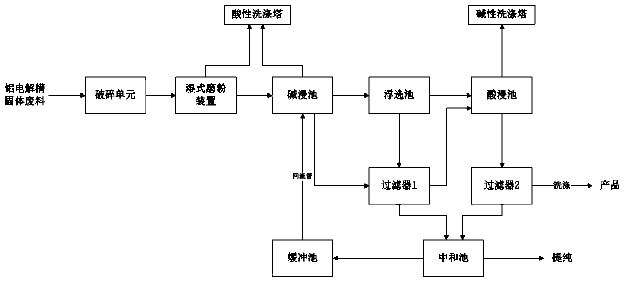
[0030] The solid waste of an aluminum electrolytic cell in a certain factory is manually screened to initially separate the waste cell lining from the anode carbon slag and the waste cathode carbon block, according to figure 1 The flow of the processing system is shown for processing:

[0031] 1. Treatment of anode carbon slag and waste cathode carbon block

[0032] (1) The anode carbon slag and the spent cathode carbon block are initially crushed into particles with a particle size of less than 500 mm by the hammer crusher in the crushing unit, and then crushed to 80-100 mesh with a Raymond mill, with a mass percentage concentration of 10% NaOH aqueous solution (or Ca(OH) 2 , CaO, KOH, Na 2 CO 3 、K 2 CO 3 Any one or more kinds of aqueous solutions) are mixed, put into a wet ball mill to grind to a particle size of ≤200 mesh, and then sent to an alkali immersion tank, and the gas generated by the wet mill is sent to an acid scrubber to be washed and discharged after reach...

Embodiment 2

[0045] The solid waste of an aluminum electrolytic cell in a certain factory is manually screened to initially separate the waste cell lining from the anode carbon slag and the waste cathode carbon block, according to figure 1 The flow of the processing system is shown for processing:

[0046] 1. Treatment of anode carbon slag and waste cathode carbon block

[0047] (1) The anode carbon slag and the spent cathode carbon block are initially crushed into particles with a particle size of less than 500 mm by the hammer crusher in the crushing unit, and then crushed to 80-100 mesh with a Raymond mill, with a mass percentage concentration of 12% KOH aqueous solution (or Ca(OH) 2 , CaO, NaOH, Na 2 CO 3 、K 2 CO 3 Any one or more kinds of aqueous solutions) are mixed, put into a wet ball mill to grind to a particle size of ≤200 mesh, and then sent to an alkali immersion tank, and the gas generated by the wet mill is sent to an acid scrubber to be washed and discharged after reach...

Embodiment 3

[0060] The solid waste of an aluminum electrolytic cell in a certain factory is manually screened to initially separate the waste cell lining from the anode carbon slag and the waste cathode carbon block, according to figure 1 The flow of the processing system is shown for processing:

[0061] 1. Treatment of anode carbon slag and waste cathode carbon block

[0062] (1) The anode carbon slag and the spent cathode carbon block are initially crushed into particles with a particle size of less than 500 mm by the hammer crusher in the crushing unit, and then crushed to 80-100 mesh with a Raymond mill, with a mass percentage concentration of 15% Na 2 CO 3 Aqueous solution (or Ca(OH) 2 , CaO, KOH, NaOH, K 2 CO 3 Any one or more kinds of aqueous solutions) are mixed, put into a wet ball mill to grind to a particle size of ≤200 mesh, and then sent to an alkali immersion tank, and the gas generated by the wet mill is sent to an acid scrubber to be washed and discharged after reach...


PUM

PropertyMeasurementUnit
particle diameteraaaaaaaaaa

Abstract

The invention belongs to the technical field of electrolytic aluminum solid waste resource treatment, and particularly discloses a solid waste recycling treatment system and method for an aluminum electrolysis cell. The system comprises a crushing unit, a wet grinding device, an alkaline leaching tank, a flotation tank, a filter 1, an acid leaching tank, a filter 2, a neutralizing tank, a buffer tank and an exhaust gas treatment system. The invention further provides a method for treating the solid waste of the aluminum electrolysis cell by utilizing the treatment system, which comprises the following steps of crushing, wet grinding, alkaline leaching, floatation, acid leaching, neutralization, purification. According to the system and method, the aluminum electrolysis cell waste tank liner, the waste cathode carbon block and the anode carbon slag can be efficiently treated and finally obtain a carbon powder with high purity, a cryolite, a regenerated silica sand and a sodium sulfate products, the cyanide and the waste gas are subjected to harmless treatment in the treatment process, no waste water is discharged, and the harmless resource reutilization of the solid waste of the aluminum electrolysis cell is really realized.

Description

technical field [0001] The invention belongs to the technical field of solid waste resource treatment of electrolytic aluminum, and in particular relates to a system and method for recycling solid waste of an aluminum electrolytic cell. Background technique [0002] The aluminum electrolytic cell needs to be overhauled after 4-7 hours of operation, and a large number of waste cathode carbon blocks, waste refractory materials, waste insulation materials, etc. are removed, and a certain amount of waste anode carbon slag is produced during the electrolysis process. At present, electrolytic aluminum plants mostly use open-air stacking or landfill methods to process electrolytic aluminum solid waste. The soluble fluoride and cyanide contained in it not only pollute the atmosphere, but also flow into rivers with rainwater, infiltrate into underground polluted soil, groundwater, and surface water. It will cause great harm to the surrounding ecological environment and human health. ...

Claims


Application Information

Patent Timeline
Patent Type & Authority Applications(China)
IPC IPC(8): B09B3/00B09B5/00
Inventor 夏仁江杨川曾子平雷朝快李乔丽黄照昊周俊宇叶智青徐广标
Owner ASIA PACIFIC ENVIRONMENTAL CORP
Why Eureka
Try Eureka