

Method of forming and separately exporting single particle wrapped drop in micro-fluidic chip
A microfluidic chip and particle technology, applied in the field of microfluidics, can solve the problems of low throughput, short detection time, slow progress, etc., and achieve the effects of low impact on cell activity, reduced operating costs, and fast pipetting speed
- Summary
- Abstract
- Description
- Claims
- Application Information
AI Technical Summary
Problems solved by technology
Method used
Image

Examples
Embodiment 1
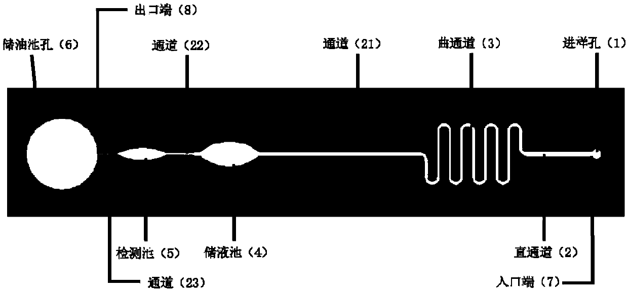
[0062] 1. Preparation of microfluidic chip:
[0063] ①Use the method of ultrasonic drilling to punch the sample injection hole and the reservoir hole on the upper quartz glass, and the hole spacing is according to the channel length. The upper layer of quartz glass is a smooth plane with a thickness of 0.5-1 mm and no etching pattern. (The sequence of the upper and lower layers of quartz glass depends on the optical path of the optical tweezers. Since the microscope used in this experiment is an upright microscope, the optical path of the optical tweezers passes through the chip from top to bottom, so it is necessary to ensure that the upper surface of the chip is a smooth optical surface, so the upper layer is smooth. Quartz glass, the quartz glass with engraved channels is on the lower level)
[0064] ②The surface of the lower quartz glass is etched according to the channel design, and the channel height is about 15-50 microns.
[0065] ③The two layers of glass are aligned...
Embodiment 2
[0072] The formation and export of the target single particle-encapsulated droplet, the schematic diagram of the steps is shown in Figure 4 .
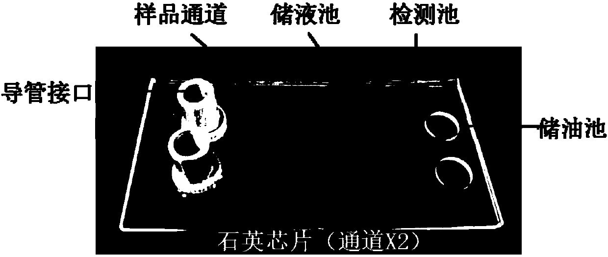
[0073] ①Inject the oil phase into the oil reservoir at the outlet end of the sample channel (generally, mineral oil containing surfactant is used).
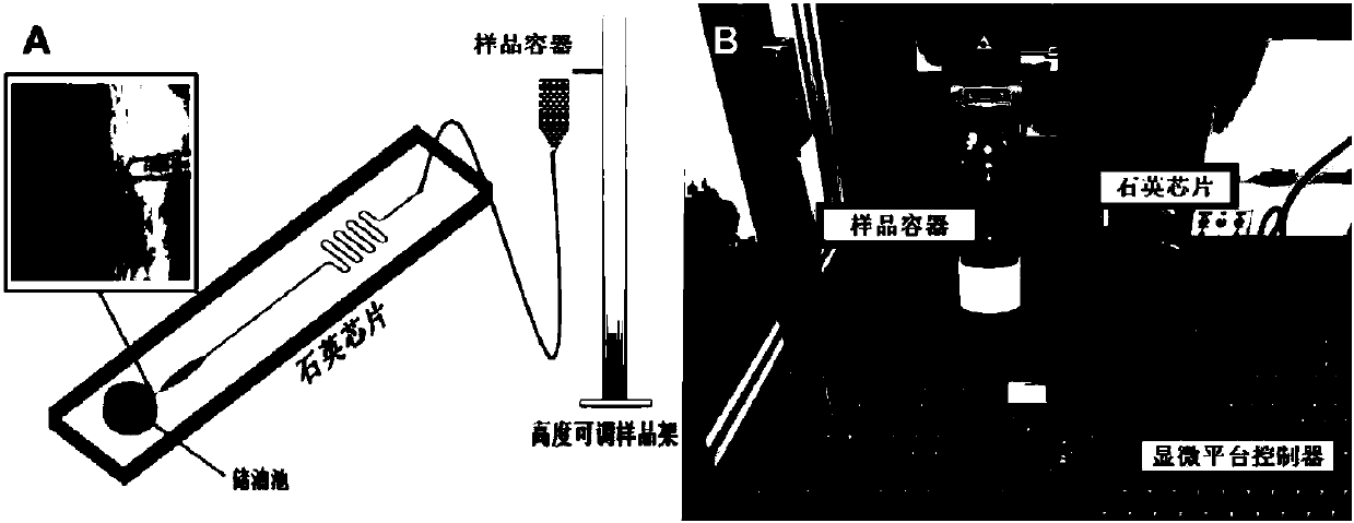
[0074] ②Using the method of static pressure injection, the particle phase (cell phase is used in this example) solution is injected into the channel of the chip through the injection port, and the height of the sample holder is adjusted to h0 so that the interface between the cell phase and the oil phase of the sample outlet Stable and stationary near the mouth.
[0075] ③ Collect the characteristic map of a single cell in the detection cell (such as Raman spectrum, 532nm laser), and capture the desired target cells through optical tweezers (such as 1064nm laser), move the microfluidic chip, and drag the target cells to the water phase Near the interface with the oil phase.
[0076] ④...
Embodiment 3
[0080] DNA amplification and electrophoretic detection of isolated single cells.
[0081] The liquid droplets separated in Example 2 are observed under the 50X objective lens, and it can be seen that single cells are successfully wrapped in the liquid droplets. This method is applicable to cells of different sizes, from about one micron to tens of microns, such as Figure 5 G and Figure 5 H is the encapsulation of Escherichia coli cells and yeast cells in the droplet using this method, respectively. Since the density of the mineral oil used in this method is lower than that of the cell suspension (water), the droplets will be automatically distributed at the bottom of the capillary during the transfer of the droplets, and it is only necessary to touch the capillary containing the droplets to the wall of the test tube or centrifuge tube. Droplets can be exported, which makes the transfer process more successful and simpler.
[0082] Centrifuge the single-cell-encapsulated dr...
PUM
 Abstract
Description
Claims
Application Information