Method for treating tank bottom oil-containing sludge and treatment system

A treatment system and technology for oily sludge, applied in pyrolysis treatment of sludge, sludge treatment, separation methods, etc., can solve the problems of many skids, increased treatment cost, and long process.

Inactive Publication Date: 2019-07-23
成都启川新能源科技有限公司
View PDF5 Cites 2 Cited by
  • Summary
  • Abstract
  • Description
  • Claims
  • Application Information

AI Technical Summary

Problems solved by technology

The chemical hot washing method is mainly through the process of drum screening-aeration and grit settling-heating-dosing conditioning-solid-liquid separation. This method requires a large amount of chemicals and steam. Hydrocarbons < 5%, can partially reduce the amount of oily sludge, and the process is long and there are many skids, so only centralized treatment methods can be used instead of decentralized treatment
Incineration is the use of natural gas or heavy oil to ignite oily sludge at high temperature, and the hydrocarbons in the oily sludge are decomposed to achieve harmless treatment. However, the smoke generated by incineration is large and the treatment cost is high; and ash residues are hazardous wastes that require secondary treatment, which increases treatment costs
Thermal desorption is mainly to heat the oily sludge through the partition wall under the condition of anaerobic or anoxic, and volatilize the water and hydrocarbons in the oily sludge according to the water in the oily sludge and the boiling points of various hydrocarbons. The tar produced during the desorption process is easy to coke in the inner wall of the reactor, leading to equipment failure and the actual processing capacity of the thermal desorption devices currently on the market is far less than the designed processing capacity, so the oily sludge cannot be treated within the expected time. Increased processing costs

Method used


Image

  • Method for treating tank bottom oil-containing sludge and treatment system
  • Method for treating tank bottom oil-containing sludge and treatment system
  • Method for treating tank bottom oil-containing sludge and treatment system

Examples


Embodiment 1

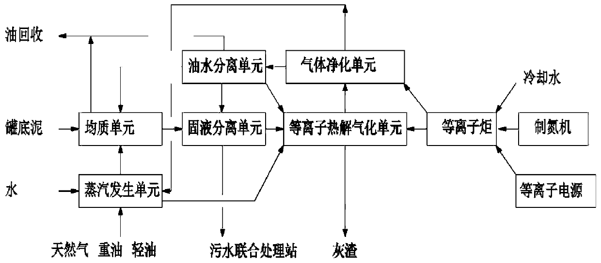
[0056] A tank bottom oily sludge treatment system, such as figure 1 As shown, it consists of a homogeneous unit, a solid-liquid separation unit, a plasma pyrolysis gasification unit, a gas purification unit, an oil-water separation unit and a steam generation unit;

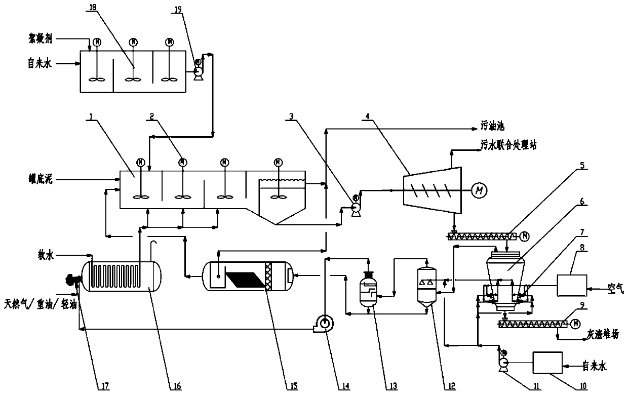
[0057] The homogenizing unit includes a dosing device 18 and a homogenizing tank 1, and the dosing device communicates with the homogenizing tank to add a degreaser or flocculant required for processing in the homogeneous phase; the homogenizing tank is equipped with Stirrer, homogenizing tank consists of 2 reaction chambers, suspension chamber and oil chamber. The dosing device is composed of a hopper, a metering screw, a solution tank, an agitator and a dosing pump 19. After the medicine is metered by the metering and metering screw, it enters the solution tank from the hopper, and is mixed and stirred with someone to obtain a medicine material liquid. Pump into the homogenization tank.

[0058] The solid-liqu...

Embodiment 2

[0064]Adopt embodiment 1 processing system to process the oily sludge at the bottom of the oil storage tank as follows:

[0065] (1) homogeneous

[0066] The oily sludge cleaned out of tank cleaning is transported to the homogenization tank 1 through the conveying equipment (it can be a screw pump or a screw conveyor). The homogenization tank includes 2 reaction chambers, a suspension chamber and an oil chamber, and PAM, etc. are added to the dosing In the device 18, the water and the medicament are uniformly mixed by the agitator, and then transported to the reaction chamber of the homogenizing tank 1 by the dosing pump 19. The oily sludge is diluted with hot water separated from the oil-water separation unit, and the solid-liquid ratio in the homogeneous tank reaches 1:4 to 1:6 according to the solid content of the cleaned tank bottom sludge. The steam in the homogeneous tank is fed into the homogeneous tank so that the temperature in the homogenized unit reaches 60-80 ° C....


PUM


Abstract

The invention provides a method for treating tank bottom oil-containing sludge and an oil-containing sludge treatment system. The method comprises the procedures of homogenizing treatment, solid-liquid separation, plasma thermal pyrolysis, gas purification and oil-water separation. The system comprises a homogenizing unit, a solid-liquid separation unit, a plasma thermal pyrolysis unit, a gas purifying unit, an oil-water separation unit and a steam generation unit. By adopting the method, the treatment cost is lowered. The system is simple and convenient in treatment operation, is low in equipment requirement, and can complete innocent treatment of tank bottom sludge while completing tank cleaning (TPH (Total Petroleum Hydrocarbons) in the treated sludge is less than 0.03 percent).

Description

technical field [0001] The invention belongs to the field of sludge treatment, and in particular relates to a method for treating oily sludge at the bottom of a tank. Background technique [0002] The large tanks in the oil field joint station and other stations need to be cleaned. The cleaned bottom sludge has a high oil content and is relatively large in quantity. If the tank bottom sludge is transported outside for treatment, it will involve loss of crude oil and high the transfer fee. And in the process of transfer, if the transfer vehicle is not tightly sealed, it will release a huge irritating smell during the transfer, which will affect the air environment quality on the way. If it is piled up in the station without treatment, it will not only pollute the local environment, but also greatly waste the limited oil resources. [0003] Plasma is the fourth state different from solid state, liquid state and gaseous state. It has unique physical and chemical properties. P...

Claims


Application Information

Patent Timeline
IPC IPC(8): C02F11/00C02F11/10C02F11/18C10G11/00C10K1/10C10K1/02B01D17/032
CPCB01D17/0214C02F11/00C02F11/10C02F11/18C10G11/00C10K1/02C10K1/101Y02W10/40
Inventor 雷光玖张贤彬
Owner 成都启川新能源科技有限公司
Why Eureka
Try Eureka