
Urease-driven tank-shaped micro-nano motor and preparation method thereof

A micro-nano, micro-nano particle technology, applied in microstructure devices, welding equipment, manufacturing tools and other directions composed of components that move relative to each other, can solve the problems of low movement rate and weak driving force, and achieve adjustable movement behavior. , the effect of strong driving force and simple preparation method

Active Publication Date: 2019-08-30
WUHAN UNIV OF TECH
View PDF5 Cites 6 Cited by
  • Summary
  • Abstract
  • Description
  • Claims
  • Application Information

AI Technical Summary

Problems solved by technology

[0005] The technical problem solved by the present invention is: the existing urease drives the micro-nano motor, the driving force is weak, the movement speed is low, and the movement direction cannot be adjusted independently by sensing the change of the chemical signal in the environment

Method used


Image

  • Urease-driven tank-shaped micro-nano motor and preparation method thereof
  • Urease-driven tank-shaped micro-nano motor and preparation method thereof
  • Urease-driven tank-shaped micro-nano motor and preparation method thereof

Examples


Embodiment 1

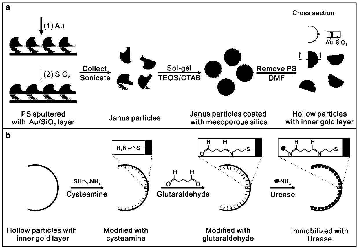
[0024] The preparation process of urease-driven pot-shaped micro-nanomotor is as follows: figure 1 As shown, it mainly includes two parts: (1) preparation of pot-shaped micro-nano particles, and (2) modification of urease on the inner surface of pot-shaped micro-nano particles.

[0025] (1) Preparation of jar-shaped micro-nanoparticles. First, after cleaning the glass slide, use oxygen plasma for hydrophilic treatment; then, drop 50 μL of PS microsphere ethanol suspension (2.3 μm, 10 mg / mL) onto the glass slide, and a single layer of PS microspheres can be formed after the ethanol evaporates. ball. Use the magnetron sputtering DC power supply to spray the gold layer for 50 seconds, and the RF power supply to spray the silicon dioxide for 40 seconds to obtain double-sided God particles. Disperse the prepared Shuangmianshen particles in 2mL deionized water, add 4mg TEOA, 7.4mg CTAB, 10μLTEOS in turn, react at 80°C for 2h, collect by centrifugation, wash with DMF 5 times, shake...

Embodiment 2

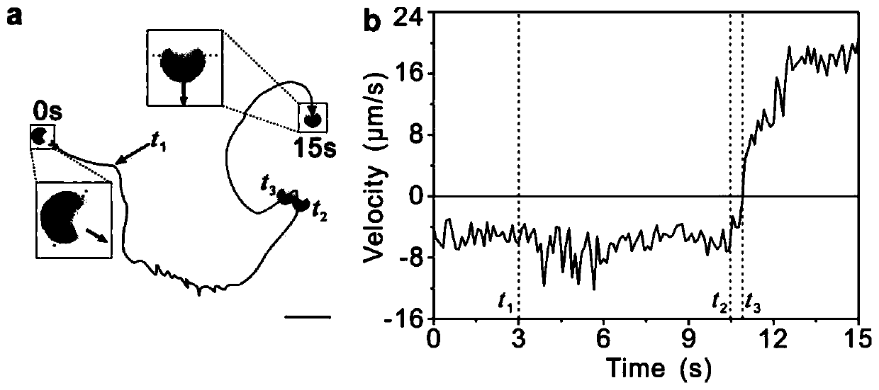
[0029] The urease-driven pot-shaped micro-nanomotor obtained in Example 1 was placed in 0.6 mM urea solution, and 50 mM urea solution was added after its movement became stable. Its trajectory is as image 3 As shown in a, before adding 50mM urea solution, urease drives the micro-nano motor to move towards the opening direction, and after adding 50mM urea solution, it moves back to the opening direction, and its real-time speed changes as follows image 3 As shown in b.

Embodiment 3

[0031] The urease-driven tank-shaped micro-nanomotor obtained in Example 1 was placed in a 5 mM urea solution, and deionized water was added after its motion became stable. Its trajectory is as Figure 4 As shown in a, before deionized water is added, urease drives the tank-shaped micro-nano motor to move away from the opening direction, and after adding deionized water, it moves towards the opening direction, and its real-time speed changes as follows Figure 4 As shown in b.


PUM

PropertyMeasurementUnit
Particle sizeaaaaaaaaaa
Opening sizeaaaaaaaaaa
Thicknessaaaaaaaaaa

Abstract

The invention discloses a urease-driven tank-shaped micro-nano motor and a preparation method thereof. The urease-driven tank-shaped micro-nano motor is relatively strong in driving force and can adaptively change the movement direction by sensing the change of fuel concentration. The urease-driven pot-shaped micro-nano motor is a hollow pot-shaped micro-nano particle containing urease molecules inside. The shape of the pot-shaped micro-nano particles is of a pot-shaped structure with an opening in one end, and the pot-shaped micro-nano particles can be prepared through a template etching method. The urease-driven pot-shaped micro-nano motor can be obtained by coupling urease molecules into a pot-shaped structure through a glutaraldehyde coupling technology. The urease-driven tank-shaped micro-nano motor has the advantages of being good in biocompatibility, high in driving force, capable of automatically adjusting the moving direction of the motor by sensing the change of the fuel concentration in the surrounding environment and capable of being used for biosensing and drug transportation.

Description

technical field [0001] The invention relates to the technical field of preparation of micro-nano devices, in particular to a urease-driven pot-shaped micro-nano motor with a strong driving force and which can adjust its movement direction by sensing changes in fuel concentration. Background technique [0002] A micro-nano motor is a micro-nano device that can convert other forms of energy in the environment into mechanical motion at the micro-nano scale and perform various tasks. Due to the unique autonomous motion performance of micro-nano motors, which can load, transport and release various micro-nano goods at the micro-nano scale, they have great application prospects in biomedical fields such as biosensing, active drug delivery, and microsurgery. [0003] Among them, the enzyme-driven micro-nano motor can use the substances in the body fluid as fuel, has good biocompatibility, does not need to carry its own fuel, and has the advantages of long exercise life. The enzyme...

Claims


Application Information

Patent Timeline
IPC IPC(8): B81B5/00B81C3/00
CPCB81B5/00B81C3/00
Inventor 罗明冯有增官建国
Owner WUHAN UNIV OF TECH
Learn More