Preparation method of dielectric substance with high energy storage density

A technology of dielectric material and high energy storage density, applied in the direction of fixed capacitor dielectric and components of fixed capacitor, etc., can solve the problems of large leakage current, high cost, low working voltage, etc., to improve energy storage density and energy storage efficiency , Improve the effect of breakdown field strength

Inactive Publication Date: 2019-09-13
HUAZHONG UNIV OF SCI & TECH +1
View PDF6 Cites 7 Cited by
  • Summary
  • Abstract
  • Description
  • Claims
  • Application Information

AI Technical Summary

Problems solved by technology

A supercapacitor is a new type of energy storage device between a dielectric capacitor and a battery. It has relatively considerable energy storage density and power density, but it also has low operating voltage (less than 4V), large leakage current, complex structure, and high cost. shortcoming

Method used


Image

  • Preparation method of dielectric substance with high energy storage density
  • Preparation method of dielectric substance with high energy storage density
  • Preparation method of dielectric substance with high energy storage density

Examples


Embodiment 1

[0033]A method for preparing a high energy storage density dielectric material, comprising the following steps:

[0034] (1) SrTiO 3 The nanoparticles were dried in an oven, and the dried SrTiO 3 Add the nanoparticles into absolute ethanol, then pour the mixture into an ultrasonic disperser for ultrasonic dispersion, and then add absolute ethanol to 500mL to obtain the mixed solution A for later use;

[0035] (2) Add ammonia water and tetraethyl orthosilicate to the prepared mixed solution A, and stir at room temperature, then use a centrifuge for high-speed centrifugation, and then centrifugally wash the obtained powder with deionized water to obtain a powder Crude product standby;

[0036] (3) Put the obtained powder crude product into an oven for drying, and after drying, it is calcined to remove crystal water to obtain SiO 2 @ST Nanoparticles;

[0037] (4) The prepared SiO 2 @ST nanoparticles are dispersed in a dopamine hydrochloride solution with a concentration of ,...

Embodiment 2

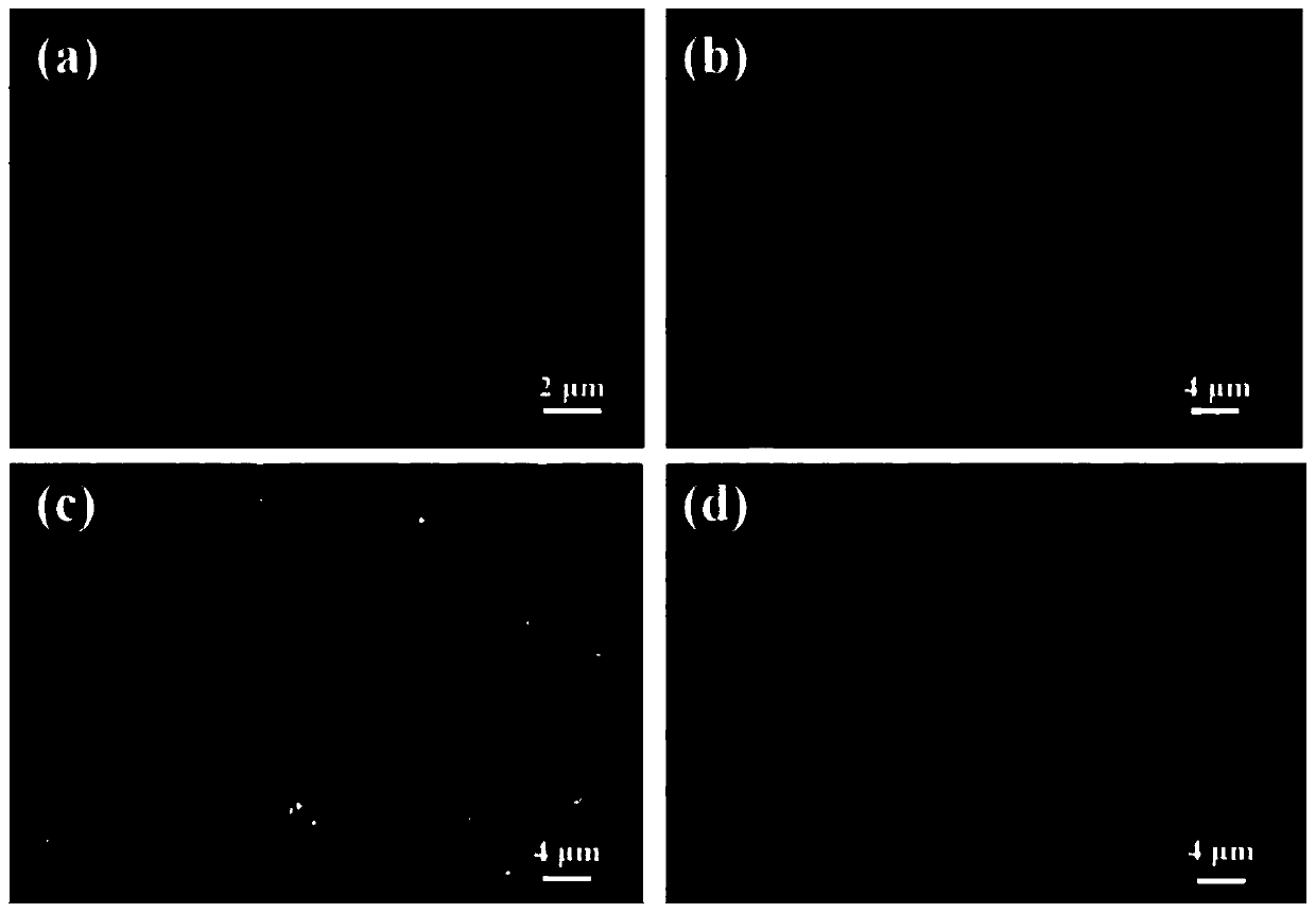
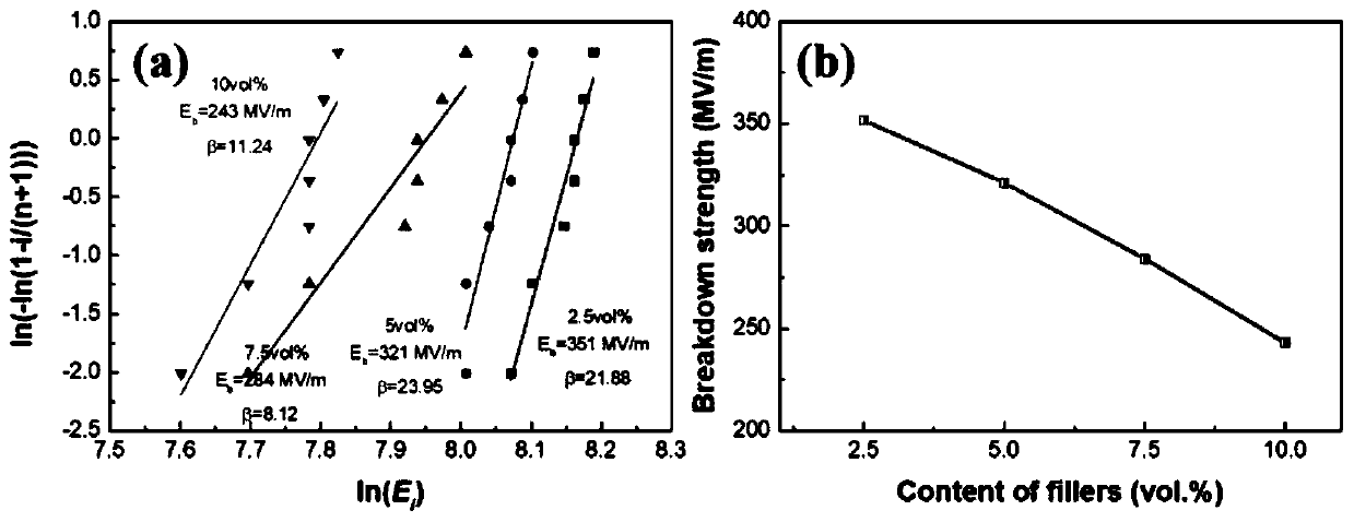
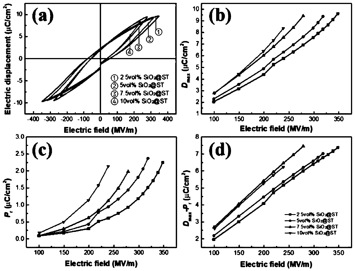
[0042] Prepare SiO according to Example 1 2 Dielectric material SiO with volume fractions of @ST of 2.5vol%, 5vol%, 7.5vol% and 10vol%, respectively 2 @ST / P(VDF-CTFE), and conduct electrical performance test on it. Circular gold electrodes with a diameter of 2.5 mm were sputtered on both sides of the dielectric material. In order to characterize the quality of the dielectric material, the dispersion of its nanoparticles and the defects in the dielectric material were analyzed by scanning electron microscopy. The room temperature electric displacement-electric field curve is measured by a comprehensive ferroelectric tester. The test temperature is room temperature and the test frequency is 100Hz. Each group of samples is tested at least 8 times to ensure the reliability of the results. The energy storage density and energy storage efficiency are calculated from the electric displacement-electric field curve. The test results are as follows:

[0043] (1) SiO 2 Microstructur...

Embodiment 3

[0050] Since the characteristics of the filler have an important effect on the polymer-based nanocomposite dielectric material, this example compares the SiO with a volume fraction of 5vol% in detail. 2 @ST and SiO 2 @BT(SiO 2 Coated BaTiO 3 ) energy storage properties of nanoparticle-filled dielectric materials. In principle, the biggest difference between the two is the dielectric constant of the filler: paraelectric ST (SrTiO 3 ) has a dielectric constant of about 300, much smaller than the ferroelectric BT (BaTiO 3 ). According to the general law, ST with small dielectric constant cannot produce large electric displacement. However, if Figure 5 The experimental results shown in (a) show that the difference between the maximum electric displacement Dmax of the two is not obvious. Under the low electric field, the Dmax values ​​of the two are almost very close. 2 The maximum potential displacement of @ST / P(VDF-CTFE) is only higher than that of SiO 2 @BT / P(VDF-CTFE) is ...


PUM

PropertyMeasurementUnit
thicknessaaaaaaaaaa
strengthaaaaaaaaaa
diameteraaaaaaaaaa

Abstract

The invention provides a preparation method of a dielectric substance with a high energy storage density, and relates to the technical field of film material production. The method comprises the following steps of: ultrasonic mixing dispersion, mixed centrifugal washing, drying and calcining, mixed centrifugal washing, dispersing and mixing, strickling, drying and heat treatment, and quenching anddrying. According to the invention, SrTiO3 is used as a filler of the dielectric substance, is coated and modified with SiO2 and dopamine in order to effectively improve the energy storage density, the energy storage efficiency and the breakdown field strength of the dielectric substance, the highest energy storage performance of the prepared dielectric substance under the electric field strengthof 350 MV/m reaches 11.42J/cm3, and the highest energy storage efficiency reaches 55.04%.

Description

technical field [0001] The invention relates to the technical field of film material production, in particular to a method for preparing a dielectric material with high energy storage density. Background technique [0002] As the world's energy and environmental problems become increasingly serious, the development of efficient, green and pollution-free new energy technologies has become the focus of attention of countries all over the world. Disadvantages such as high degree of dispersion, instability, and intermittency make it difficult for wind energy, solar energy, and tidal energy to be efficiently and fully utilized. Therefore, energy storage technology and devices have always been the core of new energy technology. [0003] The current mainstream energy storage devices include batteries, supercapacitors and dielectric capacitors. The three types of energy storage devices are used in different fields because of their respective characteristics. Batteries represented b...

Claims


Application Information

Patent Timeline
Patent Type & Authority Applications(China)
IPC IPC(8): H01G4/06
CPCH01G4/06
Inventor 张海波叶宝华范鹏元姜礼朱义为
Owner HUAZHONG UNIV OF SCI & TECH
Why Eureka
Try Eureka